
Page 442 - Industrial Wastewater Treatment, Recycling and Reuse
P. 442
Application of Anaerobic Membrane Bioreactor 413
10.4.1 Materials and Methods
A CSTR type of side stream configuration was used in the AnMBR for this
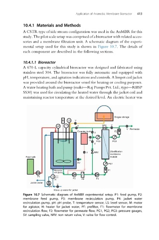
study. The pilot scale setup was comprised of a bioreactor with related acces-
sories and a membrane filtration unit. A schematic diagram of the experi-
mental setup used for this study is shown in Figure 10.7. The details of
each component are described in the following sections.
10.4.1.1 Bioreactor
A 670-L capacity cylindrical bioreactor was designed and fabricated using
stainless steel 304. The bioreactor was fully automatic and equipped with
pH, temperature, and agitation indications and controls. A limpet coil jacket
was provided around the bioreactor vessel for heating or cooling purposes.
A water heating bath and pump (make—Raj Pumps Pvt. Ltd.; type—RBSP
SS30) was used for circulating the heated water through the jacket coil and
maintaining reactor temperature at the desired level. An electric heater was
Biogas storage
M LS V
pH T V NRV V
V Permeate
Cleaning tank F2
V
V PG3 PG2
V
V NRV Ultrafiltration
membrane
Feed tank module
SV
PG1
Bioreactor F1
with jacket
P1
P2 P3
H PF
Jacket water
V
P4
Make up water for jacket
Figure 10.7 Schematic diagram of AnMBR experimental setup. P1: feed pump, P2:
membrane feed pump, P3: membrane recirculation pump, P4: jacket water
recirculation pump, pH: pH probe, T: temperature sensor, LS: level sensor, M: motor
for agitator, H: heater for jacket water, PF: prefilter, F1: flowmeter for membrane
recirculation flow, F2: flowmeter for permeate flow, PG1, PG2, PG3: pressure gauges,
SV: sampling valve, NRV: non return valve, V: valve for flow control.