
Page 83 - Inorganic Mass Spectrometry : Fundamentals and Applications
P. 83
I~du~tivel~ Coupled Plasma Mass Spe~tr~met~ 73
prevent circular current flow), is often used (as is done on the HP 4500 ICP-MS,
called Plasmashield). The extent of capacitive coupling is also a function of the rf
power, distance between the load coil and sampling plate, center gas flow rate, and
diameter of the load coil (the capacitive coupling decreases the farther the load
coil is from the plasma, i.e., the larger the inner diameter of the load coil).
The role of the sample introduction system is to convert a sample into a form that
can be effectively vaporized into free atoms and ions in the ICP. A peristaltic pump
is typically used to deliver a constant flow or sample solution (independent of
variations in solution viscosity) to the nebulizer. Several different Ends of nebu-
lizers are available to generate the sample aerosol, and several different spray
chamber designs have been used to modify the aerosol before it enters the ICP.
Gases can be directly introduced into the plasma, for example, after hydride
generation. Solids can be introduced by using electrothermal vaporization laser
or
ablation.
~neumatic ~e~ulizer/S~ray Chamber Combinations
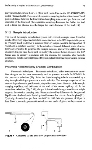
~~e~~atic ~e~ulizers. Pneumatic nebulizers, either concentric or cross-
flow designs, are the most commonly used to generate aerosols for ICP-MS. In
the concentric nebulizer (Fig. 3.4a), the liquid carrying tube is surrounded by a
ring through which gas passes at a sonic velocity. The average drop size of the
aerosol depends on the gas flow rate, ring orifice area, inner diameter of the sample
carrying capillary, and thickness of the wall of the center capillary [4]. In the
is
cross-flow nebulizer (Fig. 3.4b), the gas introduced through an orifice at a right
angle to the solution carrying tube. Shear produced by differences in the gas and
into
liquid velocities breaks the liquid up filaments that relax to form droplets [ 1 l].
Typically, the nebulizer gas flow rate is OS to 1.0 L/min at a pressure of 50 psi or
less. Most concentric, pneumatic nebulizers are made of glass, so they cannot be
Figure 4 Concentric (a) and cross-flow (b) pneumatic nebulizers.