
Page 86 - Inorganic Mass Spectrometry : Fundamentals and Applications
P. 86
76 Olesik
uptake rate [ 1 l]. The key nebulizer design parameters are the area through which
of
the nebulizer gas flows at the nebulizer tip, the inner diameter the capillary that
the liquid sample flows through, and (for concentric nebulizers) the thickness of
the wall of the center capillary [ 1 l]. There are a variety of designs of concentric,
of
cross-flow, and high-solids nebulizers. Most the concentric nebulizers are made
one
of glass and their dimensions can vary significantly from nebulizer to the next,
even of the same type [ 181. As a general rule, the gas must reach sonic veloc-
ity (approximately 320 &sec) in order to produce a fine aerosol effectively.
Cross-flow nebulizers are typically made of co~osion-resistant materials so that
even solutions containing hydrofluoric acid can be nebulized and introduced into
the ICP.
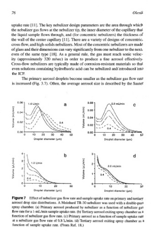
The primary aerosol droplets become smaller as the nebulizer gas flow rate
is increased (Fig. 3.7). Often, the average aerosol size is described by the Sauter
0*06 1 0.08 c
6". fl'" mL'min
'E 0.06
-r
-1
E 0.04
g
2 0*02
0.00 0.00
0 10 20 30 40 50 1 10 20 30 40 50
Droplet diameter (pm) Droplet diameter (pm)
\ b )L11 3 d
C .-
\YLfmin
P,
- 1
5
P
0 n
0 10 20 30 0 10 20 30
Droplet diameter (pm) Droplet diameter (pm)
ure 7 Effect of nebulizer gas flow rate and sample uptake rate on primary and tertiary
aerosol drop size distributions. A Meinhard TR-30 nebulizer was used with a double-pass
spray chamber. (a) Primary aerosol produced by nebulizer as a function of nebulizer gas
flow rate for a l-m.L/min sample uptake rate. (b) Tertiary aerosol exiting spray chamber as a
function of nebulizer gas flow rate. (c) Primary aerosol as a function of sample uptake rate
at a nebulizer gas flow rate of 0.8 L/min. (d) Tertiary aerosol exiting spray chamber as a
function of sample uptake rate. (From Ref. 18.)