
Page 303 - Instrumentation Reference Book 3E
P. 303
Measurement techniques: radiation thermometers 287
Figure 14.55(c) shows the graph against time of
the chopped radiation together with the resulting
electrical signal.
14.62.3 Optical (~isisnppearing Silrrinent)
fhemoineter
Optical radiation thermometers provide a simple
and accurate means for measuring temperatures
in the range 600 "C to 3000 "C. Since their opera-
tion requires the eye and judgment of an opera-
Figure 14,53 Mechanism of pyroelectriceffect
tor, they are not suitable for recording or control
purposes. However, they provide an effective way
6V = SQ/C = RASTIC (14.40) of making spot measurements and for calibration
of total radiation thermometers.
where C is the electrical capacitance between the In construction an optical radiation therm-
electrodes. The pyroelectric coefficient R is a ometer is similar to a telescope. However, a tung-
function of temperature reducing with a non-lin- sten filament lamp is placed at the focus of the
ear characteristic to zero at the Curie tempera- objective lens. Figure 13 56 shows the optical
ture. arrangement of an optical radiation therm-
When used as a detector in a radiation therm- ometer. To use the instrument the point where
ometer, radiation absorbed at the surface of the the temperature is required to be known is viewed
pyroelectric slice causes the temperature of the through the instrument. The current through the
detector to rise to a new higher level. At the start lamp filament is adjusted so that the filament
the charge on the electrodes will have leaked disappears in the image. Figure 14.57 shows
away through the external electrical circuit so how the filament looks in the eyepiece against
there will1 have been zero voltage between the the background of the object, furnace, or what-
electrodes. As the slice heats up a voltage is ever is to have its temperature measured. At (a)
detected between the two electrodes. When the the current through the filament is too high and it
device reaches its new temperature, losing heat looks bright against the light from the furnace, at
to its environment at the same rate as it is receiv- (c) the current is too IOW while at (b) the filament
ing heat by radiation, the generation of excess is at the same temperature as the background.
charge on the electrodes ceases, the charge slowly The temperature of the filament is known from
leaks awa.y through the electrical circuit, and the its electrical resistance. Temperature readout is
detected voltage returns to zero. The device achieved either by a meter measuring the current
detects the change of incident radiation. To detect through the filament or by temperature calibra-
a constant flux of radiation, Le.. to measure a tions on the control resistor regulating the current
constant temperature, it is necessary to "chop" through the lamp. The filter in the eyepiece
the incident radiation with a rotating or oscillat- shown in Figure 14.56 passes light at a wave-
ing shutter. length around 0.65 pm.
The physical construction of a pyroelectric Lamps for optical thermometers are not nor-
radiation thermometer is essentially identical to a mally operated at temperatures niuch in excess
total radiation instrument except for the location of 1500°C. To extend the range of the instru-
of the radiation-chopping shutter just in front of ment beyond this temperature a neutral filter of
the detector. Figure 14.55(aj shows the location known transmission factor can be placed in the
and Figure 14.55(b) a typical profile of the optical light path before the lamp. The measurement
chopper in a pyroelectric radiation thermometer. accuracy of an optical thermometer is typically
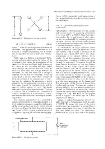
Area of electrode
High
impedance
voltmeter
Figure 14.54 Pyroelectric detector.