
Page 304 - Instrumentation Reference Book 3E
P. 304
288 Temperature measurement
-
--
_---
motor
plug and
socket
Profile of
optical chopper
U U
Chopped optical signal
( b x
1
Electrica I signa I
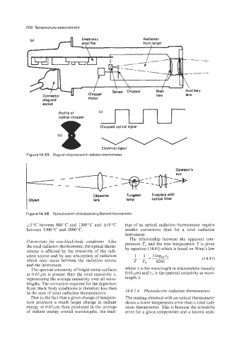
Figure 14.55 Diagram of pyroelectric radiation thermometer.
Objective Tungsten Eyepiece with
Object lens lamp optical filter
Figure 14.56 Optical system of disappearing filament thermometer.
35°C between 800°C and 1300°C and Itl0"C ings of an optical radiation thermometer require
between 1300°C and 2000°C. smaller corrections than for a total radiation
instrument.
The relationship between the apparent tem-
Corrections for non-black-body conditions Like
the total radiation thermometer, the optical therm- perature T, and the true temperature T is given
ometer is affected by the emissivity of the radi- by equation (14.41) which is based on Wien's law
ation source and by any absorption of radiation 1 1 - Xlog,, EA
which may occur between the radiation source T T, 6245 (14.41)
and the instrument.
The spectral emissivity of bright metal surfaces where X is the wavelength in micrometers (usually
at 0.65 pm is greater than the total emissivity e, 0.65 pm) and EA is the spectral emissivity at wave-
representing the average emissivity over all wave- length A.
lengths. The correction required for the departure
from black body conditions is therefore less than
in the case of total radiation thermometers. 14.6.2.4 Photoelectric radiation thermometers
Due to the fact that a given change of tempera- The reading obtained with an optical thermometer
ture produces a much larger change in radiant shows a lower temperature error than a total radi-
energy at 0.65pm than produced in the average ation thermometer. This is because the emissivity
of radiant energy overall wavelengths, the read- error for a given temperature and a known emis-