
Page 383 - Instrumentation Reference Book 3E
P. 383
366 Chemical analysis: electrochemical techniques
Amplifier a transistor amplifier which supplies feedback
input and output proportional to the bridge error sig-
nal. Zener diode stabilized and potentiometer cir-
cuits are used to provide continuous adjustment
of span, elevation, and asymmetry potential over
the entire operating range of the instrument.
The input impedance of the instrument is about
1 x 10l2Q and the current taken from the elec-
trodes less than 0.5 x 10-"A
The principle of another system, which
achieves a similar result. is shown in Figure
17.23. It uses a matched pair of field effect tran-
sistors (FETs) housed in a single can. Here the
e.m.f. produced by the measuring electrode is fed
to the gate of one of the pair. The potential which
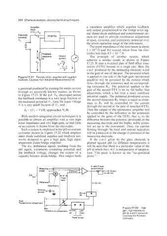
Figure 17.21 Principle of d.c. amplifier with negative is applied to one side of the high gain operational
feedback. Courtesy Kent Industrial Measurements Ltd. amplifier will be governed by the current which
flows through the transistor and its correspond-
ing resistance R3. The potential applied to the
a potential produced by passing the meter current gate of the second FET is set by the buffer bias
through an accurately known resistor, as shown adjustment, which is fed from a zener stabilized
in Figure 17.21. If the p.d. Vo, developed across potential supply. The potential developed across
the feedback resistance is a very large fraction of the second resistance R4 which is equal in resist-
the measured potential VI, then the input voltage ance to R3 will be controlled by the current
Vis a very small fraction of VI, and through the second of the pair of matched FETs.
Io = (VI - V)/R, approaches VI/R Thus the output of the operational amplifier will
be controlled by the difference in the potentials
With modern integrated circuit techniques it is applied to the gates of the FETs, that is, to the
possible to obtain an amplifier with a very high difference between the potential developed on the
input impedance and very high gain, so that little measuring electrode and the highly stable poten-
or no current is drawn from the electrodes. tial set up in the instrument. Thus, the current
Such a system is employed in the pH-to-current flowing through the local and remote indicators
converter shown in Figure 17.22 which employs will be a measure of the change of potential of the
zener diode stabilized supplies and feedback net- measuring electrode.
works designed to give a high gain, high input If the e.m.f. given by the glass electrode is
impedance diode bridge amplifier. plotted against pH for different temperatures it
The d.c. imbalance signal, resulting from the will be seen that there is a particular value of the
pH signal, asymmetry correcting potential and pH at which the e.m.f. is independent of tempera-
the feedback voltage, changes the output of a ture. This point is known as the "iso-potential
capacity balance diode bridge. This output feeds point."
Auto.
Te mpera tu re compensator
Figure17.22 High
Man.
Temperature compensator '0 *A gain, high impedance
cal. elev. pH-to-current converter.
Courtesy the Foxboro
Power supply Company.