
Page 386 - Instrumentation Reference Book 3E
P. 386
Potentiometry and specific ion measurement 369
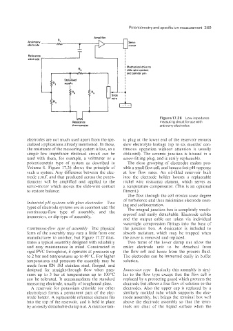
Figure17.26 Low impedance
Resistance measurrng circuit for use with
thermometer antimony electrodes
electrodes are not much used apart from the spe- ic plug at the lower end of the reservoir ensures
cialized applications already mentioned. In these, slow electrolyte leakage (up to six months’ con-
the resistance of the measuring system is low, so a tinuous operation without attention is usually
simple low impedance electrical circuit can be obtained). The ceramic junction is housed in a
used with them, for example, a voltmeter or a screw-fitting plug, and is easity replaceable.
potentiometric type of system as described in The close grouping of electrodes makes pos-
Volume 0. Figure 17.26 shows the principle of sible a small flow cell, and hence a fast pH response
such a system. Any difference between the elec- at low flow rates. An oil-filled reservoir built
trode e.m.f. and that produced across the poten- into the electrode holder houses a replaceable
tiometer will be amplified and applied to the nickel wire resistance element, which serves as
servo-motor which moves the slide-wire contact a temperature compensator. (This is an optional
to restore balance. fitment.)
The flow through the cell creates some degree
of turbulence and thus minimizes electrode coat-
Industrial pH systems with glass electrodes Two ing and sedimentation.
types of electrode systems are in common use: the The integral junction box is completely weath-
continuous-flow type of assembly. and the erproof and easily detachable. Electrode cables
immersio 1, or dip type of assembly. and the output cable are taken via individual
watertight compression fittings into the base of
Conrinuous-jlow type of assembly The physical the junction box. A desiccator is included to
form of the assembly may vary a little from one absorb moisture, which may be trapped when
manufacturer to another. but Figure 17.27 illus- the cover is removed and replaced.
trates a typical assembly designed with reliability Two turns of the lower clamp nut allow the
and easy maintenance in mind. Constructed in entire electrode unit to be detached from
rigid PVC throughout, it operates at pressures up the flow cell and hence from the process fluid.
to 2 bar and temperatures up to 60°C. For higher The electrodes can be immersed easily in buffer
temperatures and pressures the assembly may be solution.
made from EN 58J stainless steel, flanged, and
designed for straight-through flow when pres- Immersion type Basically this assembly is simi-
sures up to 3 bar at temperatures up to 100°C lar to the flow type except that the flow cell is
can be tolerated. It accommodates the standard replaced by a protecting guard which protects the
measuring electrode, usually of toughened glass. electrode but allows a free flow of solution to the
A reservoir for potassium chloride (or other electrodes. Also the upper cap is replaced by a
electrolyte) forms a permanent part of the elec- similarly molded tube which supports the elec-
trode holder. A replaceable reference element fits trode assembly, but brings the terminal box well
into the top of the reservoir, and is held in place above the electrode assembly so that the term-
by an easily detachable clamp nut. A microceram- inals are clear of the liquid surface when the