
Page 610 - Instrumentation Reference Book 3E
P. 610
592 Non-destructive testing
24.6.7 Other non-destructive testing techniques those below the optimum required to break down
the surface barriers. The technique, however, is
There are a variety of other non-destructive tech- an obvious choice to first evaluate MPI indica-
niques which have not yet gained common accept- tions in order to differentiate purely surface fea-
ance within the oil industry but are subject to tures (for example, grinding marks) from cracks.
varying degrees of investigation and experimental
use. Some of these are described below.
24.6.7.3 Bulk ultrasonic scanning
24.6.7. I Eddy current The alternative to adapting surface non-destruc-
Eddy-current techniques are described in Section tive testing methods is to use the surrounding
24.3.4. The method can, with suitable head ampli- water as a couplant to transfer a large amount
fication, be used for a search-and-follow tech- of ultrasonic energy into the structure and then
nique. Whilst it will not detect sub-surface cracks, monitor the returning energy by scanning either a
the degree of surface cleaning both on the weld single detector or the response from a tube from
and to each side is not critical. Thus substantial which acoustic energy can be used to construct a
savings in preparation and reprotection can be visual image (Figure 24.41). Such techniques are
made. experimental but initial results indicate that very
rapid inspection rates can be obtained with the
diver entirely relegated to positioning the sensor,
24.6.7.2 A.c. potential difference (ACIPD) Analysis of the returning information is made
As mentioned in Section 24.3.3, changes in poten- initially by microcomputers, which attempt to
tial difference can be used to detect surface remove the background variation and highlight
defects. This is particularly valuable under water. the signals which alter the sensor position or scan.
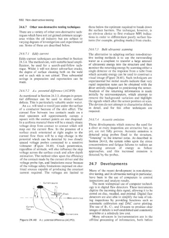
An a.c. will tend to travel just under the surface The devices do not attempt to characterize defects
of a conductor because of the skin effect. The in detail, and for this other techniques are
current flow between two contacts made on a required.
steel specimen will approximately occupy a
square with the contact points on one diagonal. 24.6.7.4 Acoustic emission
In a uniform material there will be a steady ohmic
voltage drop from contact to contact which will Those developments which remove the need for
map out the current flow. In the presence of a a diver at every inspection are attractive but, as
surface crack orientated at right angles to the yet, are not fully proven. Acoustic emission is
current flow there will be a step change in the detected using probes fixed to the structure,
potential which can be detected by two closely “listening” to the internal noise. As described in
spaced voltage probes connected to a sensitive Section 24.4.8, the system relies upon the stress
voltmeter (Figure 24.40). Crack penetration, concentrations and fatigue failures to radiate an
regardless of attitude, will also influence the step increasing amount of energy as failure
voltage across the surface crack and allow depth approaches, and this increased emission is
estimation. The method relies upon the efficiency detected by the probes.
of the contact made by the current driver and the
voltage probe tips, and limitations occur because 24.7 Developments
of the voltage safety limitations imposed on elec-
trical sources capable of producing the constant Many of the recent development in non-destruc-
current required. The voltages are limited to tive testing, and in ultrasonic testing in particular,
have been in the use of computers to control
inspections and analyze results.
+ Current source The most widespread use of computer technol-
ogy is in digital flaw detectors. These instruments
digitize the incoming data signal, allowing it to be
Crack stored on disc, recalled, and printed. Digital flaw
detectors are also able to simplify the task of tak-
-Wela centre line
ing inspections by providing functions such as
automatic calibration and DAC curve plotting.
Current The use of B-, C-, and D-scans to produce clear
flow images of defects is well established and commonly
available at a relatively low cost.
Current sink
- Many advances in instrumentation are in the
Figure 24.40 A.c. potential difference (AC/PD) off-line processing of information, both before