
Page 606 - Instrumentation Reference Book 3E
P. 606
588 Non-destructive testing
I mixture which, although increasing bright-
- - - - - - - - - - - - - - __
ness, gives a coarser-grained and hence a
Charge
level Charged plate more blurred image.
before exposure
I (3) The image produced on a fluoroscopic screen
Distance across plate is much less contrasty than that on a radio-
f fi 4 f f f + .)flncident radiation graph.
f
24.5.5.1 Image-intensification system
In fluoroscopy the main problem of low screen
brightness is due mainly to:
Distance across Dlate
(1) The low efficiency-only a fraction of the
Thickness of incident X-rays are converted into light.
powder deposit Developed plate (2) The light which is produced at the screen is
scattered in all directions, so that only a small
Distance across plate proportion of the total produced is collected
Figure 24.35 Diagrammatic representation of the by the eye of the viewer.
process of xerography.
In order to overcome these limitations, a num-
ber of image-intensification and image-enhance-
24.5.5 Fluoroscopic and image-intensification ment systems have been developed.
methods The electron tube intensifier is the commonest
type. Such instruments are commonly marketed
In fluoroscopy the set-up of source, specimen, and by Philips and Westinghouse. In this system use is
recording medium is similar to that for radio- made of the phenomenon of photoelectricity, Le.,
graphy. However, instead of film a specially con- the property possessed by some materials of emit-
structed transparent screen is used which ting electrons when irradiated by light.
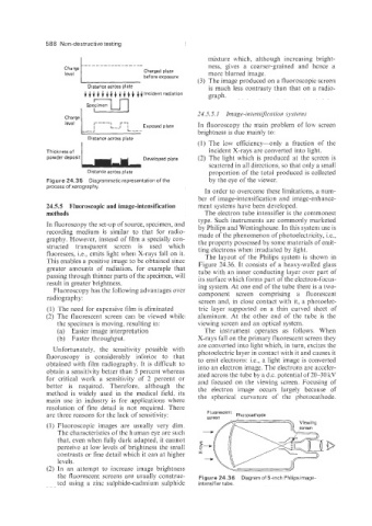
fluoresces, Le., emits light when X-rays fall on it. The layout of the Philips system is shown in
This enables a positive image to be obtained since Figure 24.36. It consists of a heavy-walled glass
greater amounts of radiation, for example that tube with an inner conducting layer over part of
passing through thinner parts of the specimen, will its surface which forms part of the electron-focus-
result in greater brightness. ing system. At one end of the tube there is a two-
Fluoroscopy has the following advantages over component screen comprising a fluorescent
radiography:
screen and, in close contact with it, a photoelec-
(1) The need for expensive film is eliminated tric layer supported on a thin curved sheet of
(2) The fluorescent screen can be viewed while aluminum. At the other end of the tube is the
the specimen is moving, resulting in: viewing screen and an optical system.
(a) Easier image interpretation The instrument operates as follows. When
(b) Faster throughput. X-rays fall on the primary fluorescent screen they
are converted into light which, in turn, excites the
Unfortunately, the sensitivity possible with photoelectric layer in contact with it and causes it
fluoroscopy is considerably inferior to that to emit electrons: Le., a light image is converted
obtained with film radiography. It is difficult to into an electron image. The electrons are acceler-
obtain a sensitivity better than 5 percent whereas
for critical work a sensitivity of 2 percent or ated across the tube by a d.c. potential of 20-30 kV
and focused on the viewing screen. Focusing of
better is required. Therefore: although the the electron image occurs largely because of
method is widely used in the medical field; its the spherical curvature of the photocathode.
main use in industry is for applications where
resolution of fine detail is not required. There
are three reasons for the lack of sensitivity: Screen Fluorescent Photocathode
(1) Fluoroscopic images are usually very dim.
The characteristics of the human eye are such
that, even when fully dark adapted, it cannot
perceive at low levels of brightness the small
contrasts or fine detail which it can at higher X
levels.
(2) In an attempt to increase image brightness
the fluorescent screens are usually construc- Figure 24.36 Diagram of 5-inch Philips image-
ted using a zinc sulphide-cadmium sulphide intensifier tube.