
Page 604 - Instrumentation Reference Book 3E
P. 604
586 Non-destructive testing
Table 24.2 Maximum thickness of steel which can be X-ray tube
radiographed with different X-ray energies
X-ray ene~gy High-sensitivity Low-sensitivity
(keV)s technique tech ique
thickness (mm) thickness (mm)
100 IO 25
150 15 50
200 25 75
250 40 90
400 75 110
1000 125 160
2 000 200 250 1
5 000 300 3 50 0 rv
30 000 300 380 w
Tube voltage
Tube current
24.5.3.1 Wire type of IQI Transformer voltage
This consists of a series of straight wires 30mm (a)
long and diameters as shown in Table 24.3. Five
models are available, the most popular con-
taining seven consecutive wires. The wires are laid
parallel and equidistant from each other and n
mounted between two thin transparent plastic
sheets of low absorption for X- or gamma rays.
This means that although the wires are fixed in
relation to each other, the IQI is flexible and thus -V
useful for curved specimens. The wires should be
of the same material as that being radiographed.
IQIs for steel, copper, and aluminum are com-
mercially available. For other materials it may
not be possible to obtain an IQI of matching
composition. In this case, a material of similar *:p
absorptive properties may be substituted.
Also enclosed in the plastic sheet are letters and Tube voltage
numbers to indicate the material type and the Transformer voltage
series of wires (Figure 24.33). For example,
4Fe10 indicates that the IQI is suitable for iron -V
and steel and contains wire diameters from 0.063
to 0.25 mm.
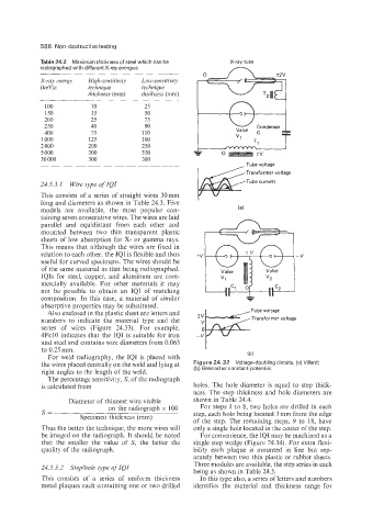
For weld radiography, the IQI is placed with Ib)
the wires placed centrally on the weld and lying at Figure 24.32 Voltage-doubling circuits. (a) Villard:
right angles to the length of the weld. (b) Greinacher constant-potential.
The percentage sensitivity, S, of the radiograph
is calculated from holes. The hole diameter is equal to step thick-
ness. The step thickness and hole diameters are
Diameter of thinnest wire visible shown in Table 24.4.
on the radiograph x 100 For steps 1 to 8, two holes are drilled in each
S= step, each hole being located 3 mm from the edge
Specimen thickness (mm)
of the step. The remaining steps, 9 to lS, have
Thus the better the technique, the more wires will only a single hole located in the center of the step.
be imaged on the radiograph. It should be noted For convenience, the IQI may be machined as a
that the smaller the value of S, the better the single step wedge (Figure 24.34). For extra flexi-
quality of the radiograph. bility each plaque is mounted in line but sep-
arately between two thin plastic or rubber sheets.
Three modules are available, the step series in each
24.5.3.2 Steplhole type of IQI
being as shown in Table 24.5.
This consists of a series of uniform thickness In this type also, a series of letters and numbers
metal plaques each containing one or two drilled identifies the material and thickness range for