
Page 600 - Instrumentation Reference Book 3E
P. 600
582 Non-destructive testing
Diffuser computer. Testing of components online has been
. Model
developed further by British Steel and by staff at
SSNDT.
Allied to the development of automatic testing
is the development of data-handling systems to
allow flaw detection to be automatic. Since the
Polarizer Analyzer volume of data to be analyzed is large, the use of
computers is essential. One danger associated
with this development is that of over-inspection.
Diffuser X/4 plate X/4 plate
The number of data values collected should be no
more than is satisfactory to meet the specification
for flaw detection.
24.4.8 Acoustic emission
Polarizer
Acoustic emission is the release of energy as a
solid material undergoes fracture or deformation.
Arc In non-destructive testing two features of acous-
source lrnaae
tic emission are important: its ability to allow
remote detection of crack formation or move-
ment at the time it occurs and to do this continu-
ously.
~~
A B FCD E G The energy released when a component under-
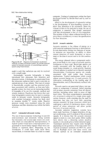
Figure 24.27 Diagrams of photoelastic visualization goes stress leads to two types of acoustic spectra;
methods. (a) Basic anisotropic system; (b) circular polarized continuous or burst type. Burst-type spectra are
system for isotropic response; (c) practical large-aperture
system using Fresnel lenses. usually associated with the leading edge of a
crack being extended, Le., crack growth. Analysis
of burst spectra is carried out to identify material
angle is such that radiation can only be received discontinuities. Continuous spectra are usually
over a small angle.
Increasingly, acoustic holography is being associated with yield rather than fracture
introduced into ultrasonic flaw detection and mechanisms. Typical mechanisms which would
release acoustic energy are: (1) crack growth, (2)
characterization. A hologram is constructed from
the ultrasonic radiation and is used to provide an dislocation avalanching at the leading edge of
optical picture of any defects. This type of system discontinuities, and (3) discontinuity surfaces rub-
bing.
is theoretically complex and has practical prob-
lems associated with stability, as does any holo- Acoustic spectra are generated when a test spe-
graphic system, but there are an increasing number cimen or component is stressed. Initial stressing
of examples of its use (for example, medical and will produce acoustic emissions from all discon-
seismic analysis). Pasakomy has shown that real- tinuities, including minor yield in areas of high
time holographic systems may be used to examine local stress. The most comprehensive assessment
welds in pressure vessels. Acoustic holography of a structure is achieved in a single stress appli-
with scanned hologram systems has been used cation; however, cyclic stressing may be used for
structures that may not have their operating
to examine double-"V" notch welds. Reactor
pressure vessels were examined using the same stresses exceeded. In large structures which have
technique and flaw detection was within the limits undergone a period of continuous stress a short
of error. period of stress relaxation will allow partial
recovery of acoustic activity.
Acoustic emission inspection systems have
24.4.7 Automated ultrasonic testing three main functions: (1) signal detection, (2) sig-
nal conditioning, and (3) analysis of the processed
The use of microcomputer technology to provide signals. It is known that the acoustic emission
semi-automatic and automatic testing systems signal in steels is a very short pulse. Other studies
has increased, and several pipe testers are avail- have shown that a detecting system sensitive
able which are controlled by microprocessors. A mainly to one mode gives a better detected signal.
typical system would have a microprocessor pro- Transducer patterns may require some thought,
grammed to record defect signals which were con- depending on the geometry of the item under test.
sidered to represent flaws. Depending on the Typical transducer materials are PZT-SA, sensi-
installation, it could then mark these flaws, tive to Rayleigh waves and shear waves, and
record them, or transmit them via a link to a main lithium niobate in an extended temperature