
Page 599 - Instrumentation Reference Book 3E
P. 599
Ultrasonics 581
spectral “signatures” of the defect echoes show photoelastic stress analysis (see Chapter 4, Sec-
significant differences. tion 4.9). Visualization works well in situations
where continuous ultrasound is being used. If a
pulsed system is used then collimation of the light
24.4.6 Other ways of presenting information
from ultrasonics beam crossing the ultrasound beam and a pulsed
light source are required.
Many other techniques of processing ultrasonic The principal advantage of a photoelastic sys-
infomation are available, and in the following the tem is its compactness and lack of protective
gener,al principles of two main groups: (1) ultrason- covering in contrast to the Schlieren system.
ic visualization or (2) ultrasonic imaging will be Photoelastic systems are also cheaper. How-
outlined. More detailed information may be found ever, the Schlieren system’s major advantage lies
in the references given at the end of this chapter. in its ability to visualize in fluids as well as in
Ultrasonic visualization makes use of two main solids. The sensitivity of photoelastic techniques
techniques: (I) Schlieren methods and (2) photo- to longitudinal waves is half that for shear waves.
elastic methods. A third method combining both Measurements with Schlieren systems have
of these has been described by D. M. Marsh in shown that the sensitivity of ultrasound visualiza-
Research Techniques in hTon-destructive Testing tion systems is particularly affected by misalign-
(1973). Schlieren methods depend on detecting ment of the beam. For example, misalignment of
the deviation of light caused by refractive index the beam in water is magnified by refraction in
gradients accompanying ultrasonic waves. In the solid. It is therefore essential to ensure firm
most cases this technique has been used in liquids. securing of transducers by clamps capable of fine
Photoelastic visualization reveals the stresses in adjustment.
an ultrasonic wave using crossed Polaroids to An alternative approach to visualization of
detect stress birefringence of the medium. Main ultrasonic waves is the formation of an optical
uses have been for particularly intense fields, such image from ultrasonic radiation. Many systems
as those in solids in physical contact with the exist in this field and, once again, a few selected
transducer. Many other methods have been tried. systems will be outlined.
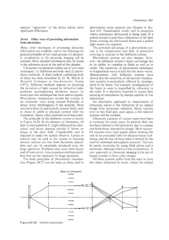
The principle of the Schlieren system is shown Ultrasonic cameras of various types have been
in Figure 24.26. In the absence of ultrasonics. all in existence for many years. In general, their use
light is intercepted by E. Light diffracted by ultra- has been limited to the laboratory due to expense
sound and hence passing outside E forms an and limitations imposed by design. Most success-
image in the dark field. Considerable care is ful cameras have used quartz plates forming the
required to make the system effective. Lenses or end of an evacuated tube for electron-beam scat-
mirrors may be used in the system as focusing tering, and the size of these tubes is limited by the
devices; mirrors are free from chromatic aberra- need to withstand atmospheric pressure. This can
tion and can be accurately produced even for be partly overcome by using thick plates and a
large apertures. Problems may exist with layout harmonic, although there is a loss in sensitivity. A
and off-axis errors. Lens systems avoid these prob- new approach to ultrasonic imaging is the use of
lems but can be expensive for large apertures. liquid crystals to form color images.
The basic principles of photoelastic visualiza- All these systems suffer from the need to have
tion ((Figure 24.27) are the same as those used in the object immersed in water. where the critical
-
Beam of ultrasound
-
-
Figure 24.26 Schlieren visualization.