
Page 601 - Instrumentation Reference Book 3E
P. 601
Radiography 583
Real-time Source
source display analysis
system computer
Transducers and preamps
v I system
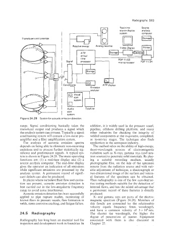
Figure 24.28 System for acoustic emission detection.
range. Signa! conditioning basically takes the addition, it is widely used in the pressure vessel,
transducer output and produces a signal which pipeline, offshore drilling platform, and many
the analysis system can process. Typically a signal other industries for checking the integrity of
conditioning system will contain a low-noise pre- welded components at the in-process, completed,
amplifier and a filter amplification system. or in-service stages. The technique also finds
The analysis of acoustic emission spectra application in the aerospace industry.
depends on being able to eliminate non-recurring The method relies on the ability of high-energy,
emissions and to process further statistically sig- short-wavelength sources of electromagnetic
nificant and predominant signals. A typical sys- radiation such as X-rays, gamma rays (and neu-
tem is shown in Figure 24.28. The main operating tron sources) to penetrate solid materials. By plac-
functions are: (1) a real-time display and (2) a ing a suitable recording medium, usually
source analysis computer. The real-time display photographic film, on the side of the specimen
gives the operator an indication of all emissions remote from the radiation source and with suit-
while significant emissions are processed by the able adjustment of technique, a shadowgraph or
analysis system. A permanent record of signifi- two-dimensional image of the surface and intern-
cant (defects can also be produced. al features of the specimen can be obtained.
In plants where turbulent fluid flow and cavita- Thus radiography is one of the few non-destruc-
tion are present, acoustic emission detection is tive testing methods suitable for the detection of
best carried out in the low-megahertz frequency internal flaws, and has the added advantage that
range to avoid noise interference. a permanent record of these features is directly
Acoustic emission detection has been successfully produced.
applied to pipe rupture studies, monitoring of X- and gamma rays are parts of the electro-
known flaws in pressure vessels, flaw formation in magnetic spectrum (Figure 24.29). Members of
welds, stress corrosion cracking, and fatigue failure. this family are connected by the relationship
velocity equals frequency times wavelength.
and have a common velocity of 3 x 10⁸m/s.
24 5 Radio g r a p h y The shorter the wavelength, the higher the
degree of penetration of matter. Equipment
Radiography has long been an essential tool for associated with them is also discussed in
inspection and development work in foundries. In Chapter 22.