
Page 605 - Instrumentation Reference Book 3E
P. 605
Radiography 587
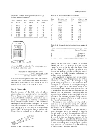
Table 24.3 Voltage-doubling circuits: (a) Villard; (b) Table 24.4 Hole and step dimensions for IQI
Greinaclner constant-potential
Step Diurneter and Step Dianietev and
Wive Diameter Wive Diameter Wire Diameter no. step thickness no. step thickness
no. (mm) no. (mm) no. (mm) (mm) (mm)
__ ~
1 0.032 8 0.160 15 0.80 1 0.125 10 1 .oo
2 0.010 9 0.200 16 1.00 2 0.160 11 1.25
3 0.050 10 0.250 17 1.25 3 0.200 12 1.60
4 0.063 11 0.320 18 1.00 4 0.250 13 2.00
5 0.080 12 0.400 19 2.00 5 0.320 14 2.50
6 0.100 13 0.500 20 2.50 6 0.400 15 3.20
7 0.125 14 0.63 21 3.20 7 0.500 16 4.00
8 0.630 17 5.00
9 0.800 18 6.30
Table 24.5 Step and holes included in different models of
IQi
Model Step and hde sizes
A 1-6 inclusive
B 7-12 inclusive
C !3-18 inclusive
Figure 24.33 Wire-typo 101.
coated on one side with a layer of selenium
which the IQI is suitable. The percentage sensi- 30-100 pm thick. A uniform positive electric
tivity, S, is calculated from charge is induced in the selenium layer. Since
selenium has a high resistivity, the charge may
Diameter of smallest hole visible be retained for long periods provided the plate is
on the radiograph x 100 not exposed to light, ionizing radiations, or
S= unduly humid atmospheres.
Specimen thickness (mm)
Exposure to X- or gamma rays causes a leak-
For the thinner steps with two holes it is import- age of the charge from the selenium to the earthed
ant thLat both holes are visible before that diam- aluminum backing plate-the leakage at any
eter can be included in the calculation. In use, this point being proportional to the radiation dose
type is placed close to, but not on, a weld. falling on it. The process of forming the image is
shown in Figure 24.35. This latent image is de-
24.5.4, Xerography veloped by blowing a fine white powder over the
exposed plate. The powder becomes charged (by
Mainly because of the high price of silver. friction) and the negatively charged particles are
attempts have been made to replace photographic attracted and adhere to the positively charged
film as the recording medium. Fluoroscopy is one selenium, the amount attracted being propor-
such imethod but is of limited application due to tional to the amount of charge at each point on
its lack of sensitivity and inability to cope with the "latent" selenium image.
thick sections in dense materials. An alternative The image is now ready for viewing, which is
technique which has been developed and which best done in an illuminator using low-angle illu-
can produce results of comparable sensitivity to mination, and the image will withstand vibration,
film radiography in the medium voltage range but it must not be touched.
(100-250 kV) is xerography. In this process, the The process is capable of a high degree of
X-ray film is replaced by an aluminum plate image sharpness since the selenium is virtually
free of graininess, and sharpness is not affected
by the grain size of the powder. An apparent
drawback is the low inherent contrast of the
image, but there is an outlining effect on image
detail which improves the rendering of most types
of weld and casting flaws thus giving an apparent
high contrast. The overall result is that sensitivity
Figure 24.34 Stepiholetype IQI. is similar to that obtained with film.