
Page 607 - Instrumentation Reference Book 3E
P. 607
Underwater non-destructive testing 589
444 able of operation at and below the surface of the
Fluorescent screen sea. Because of high capital costs, large operating
costs, and public interest the structures are
Photoelectric layer
expected to operate all the year round and to be
re-certificated by relevant authorities and insur-
ance companies typically on a five-year renewal
4-3 basis.
I The annual inspection program must be
I planned around limited opportunities and nor-
I mally covers:
94 (1) Areas of previous repair;
I
(2) Areas of high stress;
(3) Routine inspection on a five-pear cycle
The accumulated inspection records are of
great importance. The inspection is designed to
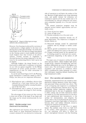
Figure 24.37 Diagram of Westinghouse image. include checks on:
intensifi’er tube and optical system.
(1) Structural damage caused by operational
incidents and by changes in seabed condi-
However, fine focusing is achieved by variation of tions;
a small positive voltage applied to the inner con- (2) Marine growth accumulation both masking
ducting layer of the glass envelope. As can be seen faults and adding extra mass to the structure;
from Figure 24.36, the electron image reproduced (3) Fatigue cracking caused by the repeated cyc-
on the viewing screen is much smaller and hence
lic loading caused by wind and wave action;
much brighter than that formed at the photo- (4) Corrosion originating in the action of salt
cathode, Further increase in brightness is
obtained because the energy imparted to the elec- water.
trons by the accelerating electric field is given up The major area of concern is within the splash
on impact. zone and just below, where incident light levels;
Although brighter, the image formed on the oxygen levels, repeated wetting/drying, and tem-
final screen is small and it is necessary to increase perature differentials give rise to the highest cor-
its size with an optical magnifier. In the Philips rosion rates. The environment is hostile to both
instrument an in-line system provides a linear equipment and operators in conditions where
magnification of nine for either monocular or safety considerations make demands on inspec-
binocular viewing. tion techniques requiring delicate handling and
As can be seen from Figure 24.37, the Westing- high interpretative skills.
house instrument is somewhat similar to that of
Phi1ip:r; but there are two important differences:
24.6.1 Diver operations and communication
Generally, experienced divers are trained as non-
(1) Westinghouse uses a subsidiary electron lens destructive testing operators rather than inspec-
followed by a final main electron lens, fine tion personnel being converted into divers. The
focusing being achieved by varying the poten- work is fatiguing and inspection is complicated
tial of the weak lens. by poor communications between diver and the
(2) Westinghouse uses a system of mirrors and supervising surface inspection engineer. These
lenses to prepare the image for final viewing. constraints lead to the use of equipment which
is either robust and provides indications which
The advantages of this system are that viewing are simple for first-line interpretation by the diver
is done out of line of the main X-ray beam and or uses sophisticated data transmission to the
the image can be viewed simultaneously by two surface for interpretation, and relegates the
observers. diver’s role to one of positioning the sensor-head.
Equipment requiring a high degree of interaction
between diver and surface demands extensive
24-61 Underwater non- training for optimum performance.
deslt ru c t ive testing The communication to the diver is speech
based. The ambient noise levels are high both
The exploration and recovery of gas and oil off- at the surface, where generators, compressors,
shore based on large fabricated structures has etc., are operating, and below it, where the
created a demand for non-destructive testing cap- diver’s microphone interacts with the breathing