
Page 602 - Instrumentation Reference Book 3E
P. 602
584 Non-destructive testing
In operation a d.c. voltage in the range 100 kV to
Wavelength Nature of radiation 2 MV is applied between a heated, spirally wound
-12 filament (the cathode) and the positively charged
-1 1 fairly massive copper anode. The anode has
-10 embedded in it a tungsten insert or target of effect-
-9 ive area 2-4mm2 and it is on to this target that
-8 the electrons are focused. The anode and cathode
-7 are placed about 50 mm apart, and the tube current
-6 is kept low (5-10mA) in order to prevent over-
-5 heating of the anode. Typical voltages for a range
-4
E of steel thicknesses are shown in Table 24.2.
E -3 . 1 ,urn = 1000 nm
D The high voltage needed to produce the X-rays
J -2 is obtained by relatively simple circuitry con-
-1 100 ,urn- sisting of suitable combinations of transformers,
0 1 mm = 1000,um-
1 1 cm = 10 rnm- rectifiers, and capacitors. Two of the more widely
2 10cm- Radar used circuits are the Villard, which produces a
3 1 m = 100 Cm- Television pulsating output, and the Greinacher, producing
4 10m- Radio an almost constant potential output. These are
5 ,oo - and similar radiation shown in Figure 24.32 along with the form of the
6 1000 m- resulting voltage. A voltage stabilizer at the 240 V
7 10 000 m, input stage is desirable.
Exposure (the product of current and time)
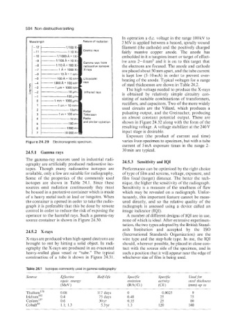
Figure 24.29 Electromagnetic spectrum. varies from specimen to specimen, but with a tube
current of 5mA exposure times in the range 2-
24.5.1 Gamma rays 30 min are typical.
The gamma-ray sources used in industrial radi- 24.5.3 Sensitivity and IQI
ography are artificially produced radioactive iso-
topes. Though many radioactive isotopes are Performance can be optimized by the right choice
available, only a few are suitable for radiography. of type of film and screens, voltage, exposure, and
Some of the properties of the commonly used film focal (target) distance. The better the tech-
isotopes are shown in Table 24.1. Since these nique, the higher the sensitivity of the radiograph.
sources emit radiation continuously they must Sensitivity is a measure of the smallness of flaw
be housed in a protective container which is made which may be revealed on a radiograph. Unfor-
of a heavy metal such as lead or tungsten. When tunately, this important feature cannot be meas-
the container is opened in order to take the radio- ured directly, and so the relative quality of the
graph it is preferable that this be done by remote radiograph is assessed using a device called an
control in order to reduce the risk of exposing the image indicator (IQI).
operator to the harmful rays. Such a gamma-ray A number of different designs of IQI are in use,
source container is shown in Figure 24.30. none of which is ideal. After extensive experimen-
tation, the two types adopted by the British Stand-
ards Institution and accepted by the IS0
24.5.2 X-rays
(International Standards Organization) are the
X-rays are produced when high-speed electrons are wire type and the step-hole type. In use, the IQI
brought to rest by hitting a solid object. In radi- should, wherever possible, be placed in close con-
ography the X-rays are produced in an evacuated tact with the source side of the specimen, and in
heavy-walled glass vessel or "tube." The typical such a position that it will appear near the edge of
construction of a tube is shown in Figure 24.31. whichever size of film is being used.
Table 24.1 Isotopes commonly used in gamma radiography
Source Effective Half-life Specific Specific Usedfor
equir. energy emission activity steel thickness
(MeV 1 (R/h/Ci ) (Cil) (mm) up to
Thulium' 'O 0.08 117 days 0 0.0025 9
Iridium'9z 0.4 75 days 0.48 25 75
~esiurn'~~ 0.6 30 yr 0.35 25 80
Cobalt6' 1.1; 1.3 5.3 yr 1.3 120 140