
Page 132 - Integrated Wireless Propagation Models
P. 132
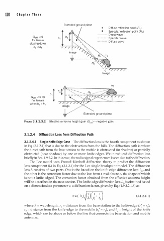
110    C h a p t e r  T h r e e


                                      Extended ground plane
                                                            •   Diffuse reflection point (R1 )
                                                            •   Specular reflection point (R2 )
                                                         --- Direct wave
                    Geffh < 0                                - ·  Specular wave
                   for terrain                           - -    Diffuse wave
                                                         •• · ••·• • ·•· ·•
                  sloping down
                        h
                    h e <  1


                                                                        /
                                                            I m age


                   Getth  < 0 for
                   flat terrain
                  when h e < h 1

                                                 Extended ground plane

               FIGURE 3.1.2.3.2  Effective a n tenna height gain (Geffh)-negative gai n .


               3.1.2.4  Diffraction Loss from Diffraction Path
               3. 1.2.4. 1   Single-Knife-Edge Case  The diffraction loss is the fourth component as shown
               in Eq. (3.1.2.1) that is due to the obstruction from the hills. The diffraction path is where
               the direct path from the base station to the mobile is obstructed (in shadow) or partially
               obstructed (near shadow) by one or more knife edges. We introduced diffraction loss
                          1
               briefly in Sec.  . 9.2.2. In this case, the radio signal experiences losses due to the diffraction.
                  The Lee model uses Fresnel-Kirchoff diffraction theory to predict the diffraction
               loss component (L) in Eq. (3 1 . 2.1) for the Lee single breakpoint model. The diffraction
                                       .
               loss L consists of two parts. One is the based on the knife-edge diffraction loss L0, and
               the other is the correction factor due to the loss from a real obstacle, the shape of which
               is not a knife edged. The correction factor obtained from the effective antenna height
               will be described in the next section. The knife-edge diffraction loss L0 is obtained based
               on a dimensionless parameter v, a diffraction factor, given by Eq. (1.9.2.2.1.6) as


                                                                                (3 1 .2.4.1)
                                                                                 .
                     'A
               where  =   wavelength, r = distance from the base station to the knife-edge (r; "' r ),
                                    1
                                                                                      1
               r2 = distance from the knife edge to the mobile (r; "' r2), and hP  h eight of the knife
                                                                      =
               edge, which can be above or below the line that connects the base station and mobile
               antennas.