
Page 134 - Integrated Wireless Propagation Models
P. 134
112 C h a p t e r T h r e e
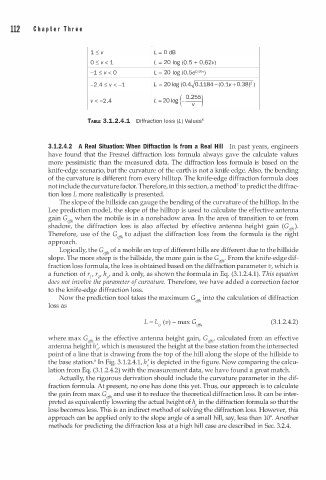
1 :o; v L = 0 dB
o :o; v < 1 L = 20 log (0. 5 + 0.62v)
-1 :o; v < 0 L = 20 log (0. 5e0 95')
2
-2 .4 :o; v < -1 L = 20 log (0.4�0.1184 - (0. 1 v + 0.38) )
L = 20 log(- ·: )
55
0
v < -2 .4
TABLE 3.1.2.4.1 Diffraction loss (L) Val u es6
3.1.2.4.2 A Real Situation: When Diffraction Is from a Real Hill In past years, engineers
have found that the Fresnel diffraction loss formula always gave the calculate values
more pessimistic than the measured data. The diffraction loss formula is based on the
knife-edge scenario, but the curvature of the earth is not a knife edge. Also, the bending
of the curvature is different from every hilltop. The knife-edge diffraction formula does
not include the curvature factor. Therefore, in this section, a method7 to predict the diffrac
tion loss L more realistically is presented.
The slope of the hillside can gauge the bending of the curvature of the hilltop. In the
Lee prediction model, the slope of the hilltop is used to calculate the effective antenna
gain Geflli when the mobile is in a nonshadow area. In the area of transition to or from
shadow, the diffraction loss is also affected by effective antenna height gain G, 1ft,) .
(
i
o
Therefore, use f the Gefftl o adjust the diffraction loss from the formula s the right
t
approach.
Logically, the G,ff/1 of a mobile on top of different hills are different due to the hillside
slope. The more steep is the hillside, the more gain is the G,1ftl" From the knife-edge dif
fraction loss formula, the loss is obtained based on the diffraction parameter v, which is
.
a function of r1, r 2 , h , and A, only, as shown the formula in Eq. (3 1 .2.4.1). This equation
P
does not involve the parameter of curvature. Therefore, we have added a correction factor
to the knife-edge diffraction loss.
Now the prediction tool takes the maximum Gefftl into the calculation of diffraction
loss as
L = L0 (v) - max G,ff/1 (3.1.2.4.2)
where max G,ff/ 1 is the effective antenna height gain, G,ff/ 1' calculated from an effective
antenna height h;, which is measured the height at the base station from the intersected
point of a line that is drawing from the top of the hill along the slope of the hillside to
the base station.8 In Fig. 3.1.2.4.1, h; is depicted in the figure. Now comparing the calcu
lation from Eq. (3 1 .2.4.2) with the measurement data, we have found a great match.
.
Actually, the rigorous derivation should include the curvature parameter in the dif
fraction formula. At present, no one has done this yet. Thus, our approach is to calculate
the gain from max G,ff/1 and use it to reduce the theoretical diffraction loss. It can be inter
preted as equivalently lowering the actual height of h in the diffraction formula so that the
P
loss becomes less. This is an indirect method of solving the diffraction loss. However, this
approach can be applied only to the slope angle of a small hill, say, less than 100. Another
methods for predicting the diffraction loss at a high hill case are described in Sec. 3.2.4.