
Page 133 - Integrated Wireless Propagation Models
P. 133
M a c r o c e l l P r e d i c t i o n M o d e l s - P a r t 2 : P o i n t - t o - P o i n t M o d e l s ll1
1 0 0°
80°
60°
40°
20°
-100°
-200° Distance to mobile (miles)
-230°
-60
-70
-80
-90
-100
0 2 3 4 5 6 7 8 9 1 0
Distance to mobile (miles)
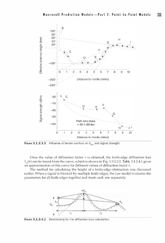
FIGURE 3.1.2.3.3 I n fluence of terrain contour on Getth and signal strength.
o
Once the value f diffraction factor v s obtained, the knife-edge diffraction loss
i
L0(v) can be found from the curve, which is shown in Fig. 1 . 9.2.2.1 . Table 3.1.2.4.1 gives
an approximation of this curve for different values of diffraction factor v.
The method for calculating the height of a knife-edge obstruction was discussed
earlier. When a signal is blocked by multiple knife edges, the Lee model evaluates the
parameters for all knife edges together and treats each one separately.
h'
e
FIGURE 3.1.2.4.1 Determining for the d i ffraction loss calculation.