
Page 158 - Integrated Wireless Propagation Models
P. 158
136 C h a p t e r T h r e e
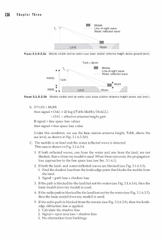
• Mobile
Line-of-sight wave
Water reflected wave
Land
FIGURE 3.1.6.3.3a Mobile visible and on water (use base station antenna height above ground level).
TxHt > MoHt
• Mobile
Line-of-sight wave
---------Water reflected wave
FIGURE 3.1.6.3.3b Mobile visible and on water (use base station antenna height above sea level).
b. If TxHt > MoHt
then signal = OAL + 20 log ((TxHt-MoHt)/HtAGL)
= OAL + effective antenna height gain
If signal > free space loss values
then signal = free space loss value
Under this condition, we use the base station antenna height, TxHt, above the
sea level, as shown in Fig. 3.1.6.3.3(b).
C. The mobile is on land and the water reflected wave is detected.
This case is shown in Fig. 3.1.6.3.4.
1 . If both reflected waves, one from the water and one from the land, are not
blocked, then a three-ray model is used. When three rays exist, the propagation
loss approaches to the free space loss (see Sec. 3.1.6.1).
2. If both the land- and water-reflected waves are blocked (see Fig. 3.1.6.3.5),
1. Find the shadow loss from the knife-edge point that blocks the mobile from
the land.
=
2. Signal p ath loss + shadow loss
3. If the path is blocked by the land but not the water (see Fig. 3.1.6.3.6), then the
basic model (two-ray model) is used.
4. If the radio path is blocked by the land but not by the water (see Fig. 3.1.6.3.7),
then the basic model (two-ray model) is used.
5. If the radio path is blocked from the terrain (see Fig. 3.1.6.3.8), then the knife
edge diffraction loss is applied.
1. Calculate the shadow loss
2. Signal = open area loss + shadow loss
3. No obstruction from buildings