
Page 162 - Integrated Wireless Propagation Models
P. 162
140 C h a p t e r T h r e e
CE = CB = CA = I
B
AB = A E
jCBA =/CAB = 45°
y
z
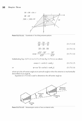
FIGURE 3.1.7.1.1.1 Coordinate of the tilting antenna pattern.
AD _ AB _ ,fiz (3.1.7.1. 1 . 4)
DF - 2([ - 2d
.
AD = A B - DB (3.1.7 1 . 1 .5)
-2 -2 -2
2CD - DF _ __!2
1
1
cos\jf = = 1 (3. . 7. . 1 .6)
2cd 2cd
.
.
Substituting Eqs. 3.1.7 1 . 1 . 1 to 3.1.7 1 . 1 . 5 into Eq. 3.1.7 1 . 1 .6, we obtain
.
2
.
s
co \j/ = 1 - cos <\> (1-cose,) (3.1.7 1 . 1 .7)
1
2
1
.
or \jf = cos- [ - c os <!> (1-cose,.)] (3.1.7 1 . 1 .8)
where \jf is the off-center angle at an azimuth angle <1> when the antenna is mechanically
downtilted at an angle e,.
Equation (3.1.7.1.1.8) is used to determine the off-center angle \jf.
---
/
/
/
/ Reduced
gain sector
/
/
/ - - - - -
/ "\ Reduced
""'
.,
ga1n
1 9 o
l sector _ - -
- - -
- -
FIGURE 3.1.7.1.1.2 Reduced-gain sector of two co-channel cells.