
Page 163 - Integrated Wireless Propagation Models
P. 163
I
t
M a c r o c e I P r e d i c t i o n M o d e I - s P a r t 2 : P o i n - t o - P o i n t M o d e I s 141
If the physically tilted angle is 8111 = 1 8 0°, then the off-center vertical angle \jf is tilted
downward dependent on the azimuth angle <j>:
0° 1 18° = 8
l 0°
<1> = 45° \jf = 12.7°
90°
This list tells us that the physically tilted angle <1> and the angle \jf are not linearly related
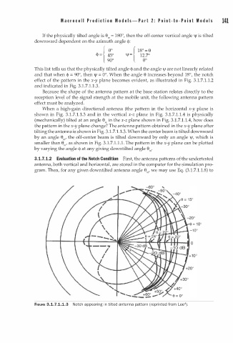
and that when <j> = 90°, then \jf = 0°. When the angle 8 increases beyond 18°, the notch
effect of the pattern in the x-y plane becomes evident, as illustrated in Fig. 3.1.7 1 . 1 . 2
.
and indicated in Fig. 3.1.7 1 . 1 . 3.
.
Because the shape of the antenna pattern at the base station relates directly to the
reception level of the signal strength at the mobile unit, the following antenna pattern
effect must be analyzed.
When a high-gain directional antenna (the pattern in the horizontal x-y plane is
shown in Fig. 3.1.7 1 . 1 . 3 and in the vertical x-z plane in Fig. 3.1.7 1 . 1 . 4 is physically
.
.
(mechanically) tilted at an angle 8111 in the x-z plane shown in Fig. 3.1.7 1 . 1 . 4, how does
.
the pattern in the x-y plane change? The antenna pattern obtained in the x-y plane after
tilting the antenna is shown in Fig. 3.1.7 1 . 1 . 3. When the center beam is tilted downward
.
by an angle 8111, the off-center beam is tilted downward by only an angle \jf, which is
.
smaller than 8111, as shown in Fig. 3.1.7 1 . 1 . 1 . The pattern in the x-y plane can be plotted
by varying the angle <j> at any giving downtilted angle 8111•
3.1. 7 1 .2 Evaluation of the Notch Condition First, the antenna patterns of the undertested
.
antenna, both vertical and horizontal, are stored in the computer for the simulation pro
gram. Then, for any given downtilted antenna angle 8111, we may use Eq. (3.1.7.1.1.8) to
e = 1 8 °
2."--., -10°
FIGURE 3.1.7.1.1.3 Notch p pearing in tilted antenna pattern (reprinted from Lee4 ) .
a