
Page 161 - Integrated Wireless Propagation Models
P. 161
I
M a c r o c e I P r e d i c t i o n M o d e I s - P a r t 2 : P o i n t - t o - P o i n t M o d e I s 139
� ··· ···· · ···
···· ··· ···· � ·· ···· ···· ·· � � .... . .
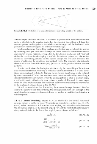
FIGURE 3.1.7.1.2 Reduction of co-channel in terference by creating a notch in the pattern.
azimuth angle. The notch will occur at the center (0°) of the beam when the downtilted
angle is tilted down to a certain angle. But the electrical downtilting will keep the
antenna pattern unchanged over the whole azimuth range, and the horizontal half
power beam width is independent of the downtilted angle.
Mechanical antenna down tilting has been an effective way to reduce interference
by confining the signal in its own coverage cell. It can reduce co-channel interference
1
significantly when a notch is developed in the direction of co-channel cell. 6 We will
define the condition for developing a notch in the antenna pattern and discuss the
impact of downtilting antenna on the system design. We will also introduce the
means of achieving the significant and optimal notch. The computer simulation is
done to illustrate the notch-developing process in dealing with different antenna
patterns.
A major contribution of reducing the interference by the down tilting of the antenna
is co-channel interference. One way to reduce co-channel interference is to use a direc
tional antenna at each cell site. In this way, the co-channel interference can be reduced
by more than one-half.3 Also, this interference can be further reduced by downtilting a
directional antenna beam pattern. When the antenna pattern is tilted to a certain angle,
a notch at the center of horizontal beam pattern is produced. The notch becomes larger
when the tilted angle increases. This notch can be effective in reducing the interference
in the co-channel cells, as shown in Fig. 3.1.7 1 .2.
.
We will review the idea that downtilting the antenna develops the notch. We also
derive the equations for demonstrating the notch phenomenon. The concept of the
notch-developing process is discussed. It can be used as a guideline for designing a
cellular system.
.
3 . 1 . 7 . 1 . 1 Antenna Downtilting Figure 3.1.7 1 . 1 . 1 shows that the normal horizontal
antenna pattern is on the x-y plane. The maximum beam form is at the x-axis (e = 0°,
m
<!> = 0°). When the antenna is downtilted at an angle e * 0°, the relationship between
m
the downtilted angle e at the azimuth angle <)> = 0° and the related off-center angle \jf
m
1
at any azimuth <)> due to the downtilted angle e can be shown as follows: 6
m
. e m d
1
1
s = (3. . 7. . 1 . 1)
mT T
DB l (3.1.7 1 . 1 . 2)
.
sin <1> sin(135°- <)>)
sin45°
.
CD = l (3 1 .7.1. 1 . 3)
sin(135 - <)>)