
Page 160 - Integrated Wireless Propagation Models
P. 160
138 C h a p t e r T h r e e
• Mobile
• Land
D W ater
FIGURE 3.1.6.3.8 Mobile is blocked.
3 . 1 . 6 .4 Conclusion
The enhancement of the Lee macrocell propagation model for the radio path over the
water ensures the inclusion of the result impacting from the water when designing a cel
lular system. Specifically, when dealing with a COMA-centric 3G system, it is imperative
to be able to predict the behavior of radio waves affected by water. The propagation over
the water can introduce an unexpected coverage and create interference problems and
thus impact the system capacity and coverage. As a result, the enhancement from the
radio path over the water has a significant effect on system resources and performance.
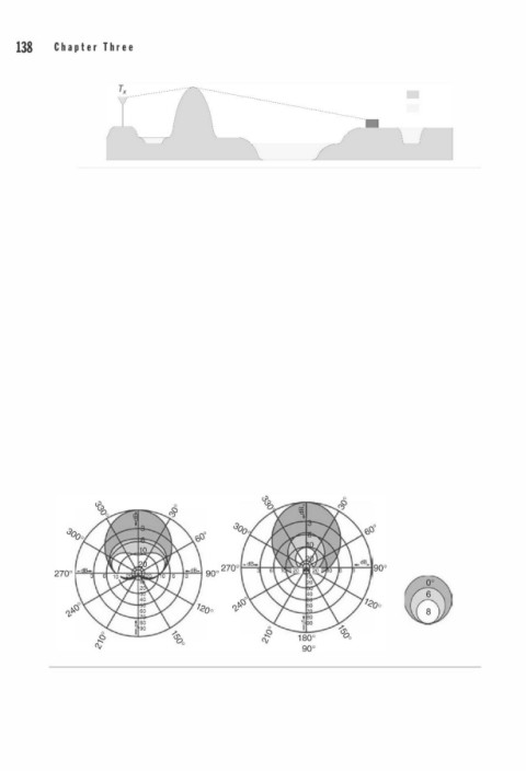
3 . 1 . 7 Effect of Antenna Orientation
3 . 1 . 7 . 1 Antenna Tilting16·17
There are two types of antenna tilting-mechanical and electrical-used in cellular
systems for reducing interference to neighboring cells. Mechanical downtilting of an
antenna will change the antenna pattern, but electrical downtilting of an antenna will
.
not. These are depicted in Fig. 3.1.7 1 . 1 .
The horizontal beam shape vary when the mechanical downtilted angle changesY
The antenna patterns measured from +90° to -90° of the beam horizontally have differ
.
ent beam shapes, as shown in Fig. 3.1.7 1 . 1 . The horizontal half-power beam width
increases as the downtilted angle increases. Also, power reduction depends on the
oo
oo
®
0
0
Color indicates tilt angle
1 8 0°
goo
FIGURE 3.1.7.1.1 Antenna downtilted horizontal pattern-mechanical (left) and electrical (right).
I
n
Courtesy of Kathrein c ., Scala Division.