
Page 164 - Integrated Wireless Propagation Models
P. 164
142 C h a p t e r T h r e e
d
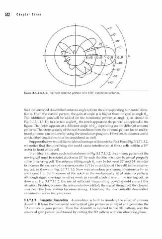
FIGURE 3.1.7.1.1.4 Vertical antenna pattern of a 120° irectional antenna.
find the corrected downtilted antenna angle \jl from the corresponding horizontal direc
tion <jl. From the vertical pattern, the gain at angle \jl is higher than the gain at angle e"'.
The additional gain will be added on the horizontal pattern at angle <jl, as shown in
Fig. 3.1.7.1.1.3. Up to a certain angle e"', the notch appears in the pattern as depicted in the
figure. The notch appears at a different angle of e"', depending on the different antenna
patterns. Therefore, a study of the notch condition from the antenna pattern for an under
tested antenna can be done by using the simulation program. However, to obtain a useful
notch, other conditions must be considered as well.
Suppose that we would like to take advantage of this notch effect. From Fig. 3.1.7.1.1.2,
we notice that the interfering site could cause interference at those cells within a 19°
sector in front of the cell.
In an ideal situation, such as that shown in Fig. 3.1.7.1.1.2, the antenna pattern of the
serving cell must be rotated clockwise 10° by such that the notch can be aimed properly
at the interfering cell. The antenna tilting angle e"' may be between 22° and 24° in order
to increase the carrier-to-interference ratio C I I by an additional 7 to 8 dB in the interfer
.
ing cell, as shown in Fig. 3.1.7 1 . 1 . 3. Now we can reduce co-channel interference by an
additional 7 to 8 dB because of the notch in the mechanically tilted antenna pattern.
Although signal coverage is rather weak in a small shaded area in the serving cell, as
shown in Fig. 3.1.7.1.1.2, the use of sufficient transmitting power should correct this
situation. Besides, because the antenna is downtilted, the signal strength of the close-in
area near the base station becomes strong. Therefore, the mechanically downtilted
antenna can serve two purposes.
3.1.7.1.3 Computer Simulation A simulator is built to simulate the effect of antenna
downtilt. It takes the horizontal and vertical gain pattern as an input and generates the
3D composite gain pattern. Then the downtilt is applied to the 3D pattern, and the
observed gain pattern is obtained by cutting the 3D pattern with our observing plane.