
Page 168 - Integrated Wireless Propagation Models
P. 168
146 C h a p t e r T h r e e
180'
(a) Horizontal (b) Vertical
/
\
'
,
, ' ' \
,
I <- 2o 'o
I \I
' "
' I
I
/
'
/
--
-
(d) Horizontal pattern at 84°
(c) 3D (--40 dB at origin) downtilt (-40 dB at origin)
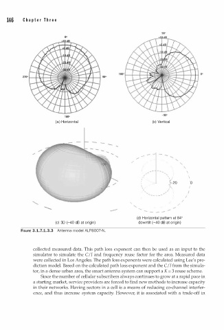
FIGURE 3.1.7.1.3.3 Antenna model ALP8007-N.
collected measured data. This path loss exponent can then be used as an input to the
simulator to simulate the C/I and frequency reuse factor for the area. Measured data
were collected in Los Angeles. The path loss exponents were calculated using Lee's pre
diction model. Based on the calculated path loss exponent and the C/I from the simula
tor, in a dense urban area, the smart antenna system can support a K = 3 reuse scheme.
Since the number of cellular subscribers always continues to grow at a rapid pace in
a starting market, service providers are forced to find new methods to increase capacity
in their networks. Having sectors in a cell is a means of reducing co-channel interfer
ence, and thus increase system capacity. However, it is associated with a trade-off in