
Page 167 - Integrated Wireless Propagation Models
P. 167
t
M a c r o c e I P r e d i c t i o n M o d e I - s P a r t 2 : P o i n - t o - P o i n t M o d e I s 145
I
180" -���·
(a) Horizontal (b) Vertical
'
/ ,
/
/
/ -
/
I
I \ \
I 'O
I
'\
' /
' /
..... /
/
- ....... _ -
(d) Horizontal pattern at 30°
(c) 3D (-20 dB at origin) (origin -20 dB)
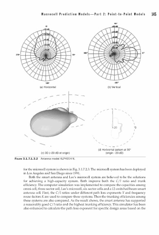
FIGURE 3.1.7.1.3.2 Antenna model ALP4014-N.
for the microcell system is shown in Fig. 3.1.7.2.3. The microcell system has been deployed
in Los Angeles and San Diego since 1991.
Both the smart antenna and Lee's microcell system are believed to be the solutions
for achieving a high-capacity system. Both improve both the C/I ratio and trunk
efficiency. The computer simulation was implemented to compare the capacities among
omni-cell, three-sector cell, Lee's microcell, six-sector cells and a 12-switched beam smart
antenna cell. First, the C/I ratios under different path loss exponents Y and frequency
reuse factors K are used to compare these systems. Then the trunking efficiencies among
these systems are also compared. As the result shows, the smart antenna has supported
a reasonably good C/ I ratio and the highest trunking efficiency. This simulator has been
also enhanced to calculate the path loss exponent for specific design areas based on the