
Page 170 - Integrated Wireless Propagation Models
P. 170
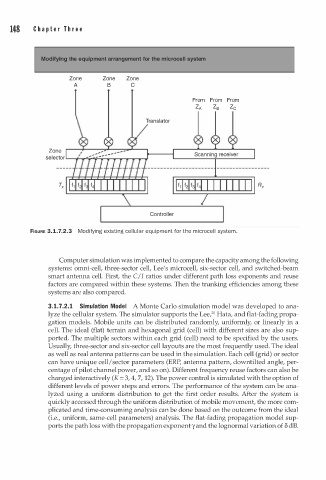
148 C h a p t e r T h r e e
Modifying the equipment arrangement for the mlcrocell systam
Zone Zone Zone
A B c
From From From
Z A Z s Z c
Zone
selector.__-+.....,.-r,,.....,,...........,.......,.......,.-�
Controller
m
FIGURE 3.1.7.2.3 Modifying existing cellular equipment for the i crocell syste .
m
Computer simulation was implemented to compare the capacity among the following
systems: omni-cell, three-sector cell, Lee's microcell, six-sector cell, and switched-beam
smart antenna cell. First, the C/I ratios under different path loss exponents and reuse
factors are compared within these systems. Then the trunking efficiencies among these
systems are also compared.
3.1.7. . 1 Simulation Model A Monte Carlo simulation model was developed to ana
2
0
lyze the cellular system. The simulator supports the Lee/ Hata, and flat-fading propa
gation models. Mobile units can be distributed randomly, uniformly, or linearly in a
cell. The ideal (flat) terrain and hexagonal grid (cell) with different sizes are also sup
ported. The multiple sectors within each grid (cell) need to be specified by the users.
Usually, three-sector and six-sector cell layouts are the most frequently used. The ideal
as well as real antenna patterns can be used in the simulation. Each cell (grid) or sector
can have unique cell/ sector parameters (ERP, antenna pattern, down tilted angle, per
centage of pilot channel power, and so on). Different frequency reuse factors can also be
changed interactively (K = 3, 4, 7, 12). The power control is simulated with the option of
different levels of power steps and errors. The performance of the system can be ana
lyzed using a uniform distribution to get the first order results. After the system is
quickly accessed through the uniform distribution of mobile movement, the more com
plicated and time-consuming analysis can be done based on the outcome from the ideal
(i.e., uniform, same-cell parameters) analysis. The flat-fading propagation model sup
ports the path loss with the propagation exponent y and the lognormal variation of 8 dB.