
Page 239 - Intelligent Digital Oil And Gas Fields
P. 239
Workflow Automation and Intelligent Control 189
Flowing BHP, psi
0 500 1000 1500 2000 2500 3000
0
THP
Model pump gradient
Pump depth, TVD ft 1000 Error Model and Sensor 5% PDP
Sensores
2000
3000
4000
5000 PIP fBHP
Extrapolated from VLP
6000
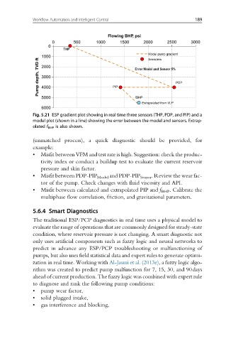
Fig. 5.21 ESP gradient plot showing in real time three sensors (THP, PDP, and PIP) and a
model plot (shown in a line) showing the error between the model and sensors. Extrap-
olated f BHP is also shown.
(unmatched process), a quick diagnostic should be provided, for
example:
• Misfit between VFM and test rate is high. Suggestion: check the produc-
tivity index or conduct a buildup test to evaluate the current reservoir
pressure and skin factor.
• Misfit between PDP-PIP Model and PDP-PIP Sensor . Review the wear fac-
tor of the pump. Check changes with fluid viscosity and API.
• Misfit between calculated and extrapolated PIP and f BHP . Calibrate the
multiphase flow correlation, friction, and gravitational parameters.
5.6.4 Smart Diagnostics
The traditional ESP/PCP diagnostics in real time uses a physical model to
evaluate the range of operations that are commonly designed for steady-state
condition, where reservoir pressure is not changing. A smart diagnostic not
only uses artificial components such as fuzzy logic and neural networks to
predict in advance any ESP/PCP troubleshooting or malfunctioning of
pumps, but also uses field statistical data and expert rules to generate optimi-
zation in real time. Working with Al-Jasmi et al. (2013e), a fuzzy logic algo-
rithm was created to predict pump malfunction for 7, 15, 30, and 90days
ahead of current production. The fuzzy logic was combined with expert rule
to diagnose and rank the following pump conditions:
• pump wear factor,
• solid plugged intake,
• gas interference and blocking,