
Page 236 - Intro Predictive Maintenance
P. 236
Process Parameters 227
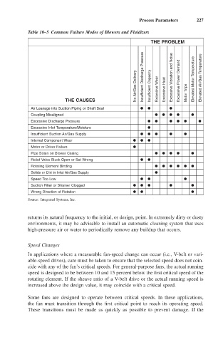
Table 10–5 Common Failure Modes of Blowers and Fluidizers
THE PROBLEM
No Air/Gas Delivery Insufficient Discharge Pressure Insufficient Capacity Excessive Wear Excessive Heat Excessive Vibration and Noise Excessive Power Demand Motor Trips Elevated Motor Temperature Elevated Air/Gas Temperature
THE CAUSES
Air Leakage into Suction Piping or Shaft Seal
Coupling Misaligned
Excessive Discharge Pressure
Excessive Inlet Temperature/Moisture
Insufficient Suction Air/Gas Supply
Internal Component Wear
Motor or Driver Failure
Pipe Strain on Blower Casing
Relief Valve Stuck Open or Set Wrong
Rotating Element Binding
Solids or Dirt in Inlet Air/Gas Supply
Speed Too Low
Suction Filter or Strainer Clogged
Wrong Direction of Rotation
Source: Integrated Systems, Inc.
returns its natural frequency to the initial, or design, point. In extremely dirty or dusty
environments, it may be advisable to install an automatic cleaning system that uses
high-pressure air or water to periodically remove any buildup that occurs.
Speed Changes
In applications where a measurable fan-speed change can occur (i.e., V-belt or vari-
able-speed drives), care must be taken to ensure that the selected speed does not coin-
cide with any of the fan’s critical speeds. For general-purpose fans, the actual running
speed is designed to be between 10 and 15 percent below the first critical speed of the
rotating element. If the sheave ratio of a V-belt drive or the actual running speed is
increased above the design value, it may coincide with a critical speed.
Some fans are designed to operate between critical speeds. In these applications,
the fan must transition through the first critical point to reach its operating speed.
These transitions must be made as quickly as possible to prevent damage. If the