
Page 293 - Introduction to Autonomous Mobile Robots
P. 293
278
a) Chapter 6
Obstacle
Obstacle
θ
b)
θ
-180° -90° 0 90° 180°
c)
θ
-180° -90° 0 90° 180°
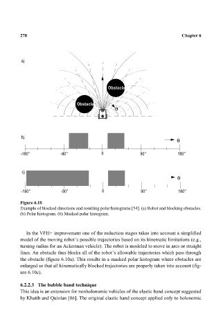
Figure 6.10
Example of blocked directions and resulting polar histograms [54]. (a) Robot and blocking obstacles.
(b) Polar histogram. (b) Masked polar histogram.
In the VFH+ improvement one of the reduction stages takes into account a simplified
model of the moving robot’s possible trajectories based on its kinematic limitations (e.g.,
turning radius for an Ackerman vehicle). The robot is modeled to move in arcs or straight
lines. An obstacle thus blocks all of the robot’s allowable trajectories which pass through
the obstacle (figure 6.10a). This results in a masked polar histogram where obstacles are
enlarged so that all kinematically blocked trajectories are properly taken into account (fig-
ure 6.10c).
6.2.2.3 The bubble band technique
This idea is an extension for nonholonomic vehicles of the elastic band concept suggested
by Khatib and Quinlan [86]. The original elastic band concept applied only to holonomic