
Page 295 - Introduction to Autonomous Mobile Robots
P. 295
280
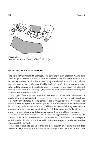
Figure 6.12 Chapter 6
A typical bubble band (Courtesy of Raja Chatila [85]).
6.2.2.4 Curvature velocity techniques
The basic curvature velocity approach. The curvature velocity approach (CVM) from
Simmons [135] enables the actual kinematic constraints and even some dynamic con-
straints of the robot to be taken into account during obstacle avoidance, which is an advan-
tage over more primitive techniques. CVM begins by adding physical constraints from the
robot and the environment to a velocity space. The velocity space consists of rotational
ω
v
velocity and translational velocity , thus assuming that the robot only travels along arcs
of circles with curvature c = ω . v ⁄
Two types of constraints are identified: those derived from the robot’s limitations in
acceleration and speed, typically v – max << v max , ω– max < ω < ω max ; and, second, the
v
constraints from obstacles blocking certain and ω values due to their positions. The
v
obstacles begin as objects in a Cartesian grid but are then transformed to the velocity space
by calculating the distance from the robot position to the obstacle following some constant
curvature robot trajectory, as shown in figure 6.13. Only the curvatures that lie within c min
and c are considered since that curvature space will contain all legal trajectories.
max
To achieve real-time performance the obstacles are approximated by circular objects
and the contours of the objects are divided into few intervals. The distance from an endpoint
of an interval to the robot is calculated and in between the endpoints the distance function
is assumed to be constant.
The final decision of a new velocity ( and ω ) is made by an objective function. This
v
function is only evaluated on that part of the velocity space that fulfills the kinematic and