
Page 97 - Introduction to Autonomous Mobile Robots
P. 97
82
Y I goal Chapter 3
X I
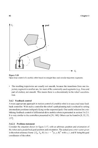
Figure 3.18
Open-loop control of a mobile robot based on straight lines and circular trajectory segments.
• The resulting trajectories are usually not smooth, because the transitions from one tra-
jectory segment to another are, for most of the commonly used segments (e.g., lines and
part of circles), not smooth. This means there is a discontinuity in the robot’s accelera-
tion.
3.6.2 Feedback control
A more appropriate approach in motion control of a mobile robot is to use a real-state feed-
back controller. With such a controller the robot’s path-planning task is reduced to setting
intermediate positions (subgoals) lying on the requested path. One useful solution for a sta-
bilizing feedback control of differential-drive mobile robots is presented in section 3.6.2.1.
It is very similar to the controllers presented in [39, 100]. Others can be found in [8, 52, 53,
137].
3.6.2.1 Problem statement
Consider the situation shown in figure 3.17, with an arbitrary position and orientation of
the robot and a predefined goal position and orientation. The actual pose error vector given
θ
,,
in the robot reference frame X Y θ,{ R R , } is e = R [ x y θ] T with xy, , and being the goal
coordinates of the robot.