Page 176 - Introduction to Computational Fluid Dynamics
P. 176

P1: IWV
                                        0 521 85326 5
                           CB908/Date
            0521853265c05
                        EXERCISES
                                REFRACTORY WALL                                    May 20, 2005  12:28 155


                                                                                          1.3 m  3.0 m


                        T      h
                           8


                                                        3.3 m
                                                        5.1 m
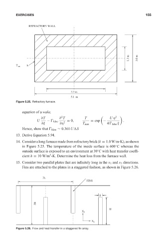
                        Figure 5.25. Refractory furnace.

                            equation of a wake,
                                                   2
                                       ∂T         ∂ T           T              U η 2
                                     U    − 
 false   = 0,          = exp −            .
                                       ∂ξ         ∂η 2         T max         4
 false ξ
                            Hence, show that 
 false ∼ 0.361U S
                        13. Derive Equation 5.94.
                        14. Consideralongfurnacemadefromrefractorybrick(k = 1.0W/m-K),asshown
                                                                                  ◦
                            in Figure 5.25. The temperature of the inside surface is 600 C whereas the
                                                                        ◦
                            outside surface is exposed to an environment at 30 C with heat transfer coeffi-
                                            2
                            cient h = 10 W/m -K. Determine the heat loss from the furnace wall.
                        15. Consider two parallel plates that are infinitely long in the x 1 and x 3 directions.
                            Fins are attached to the plates in a staggered fashion, as shown in Figure 5.26.

                                        2L
                                                                  FINS


                                                                         δ

                                    2B
                                                                                H
                                                               X 2


                                                                    X 1
                        Figure 5.26. Flow and heat transfer in a staggered fin array.
   171   172   173   174   175   176   177   178   179   180   181