
Page 180 - Introduction to Computational Fluid Dynamics
P. 180
P1: IWV
0 521 85326 5
CB908/Date
0521853265c05
EXERCISES
18 cm VANE FAN May 20, 2005 12:28 159
10 cm
66 cm
50 cm
WET PAD
FRONT GRILL
44 cm
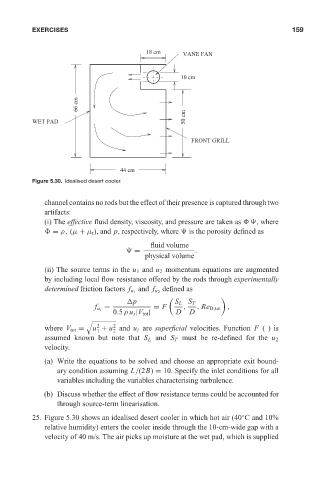
Figure 5.30. Idealised desert cooler.
channel contains no rods but the effect of their presence is captured through two
artifacts:
(i) The effective fluid density, viscosity, and pressure are taken as , where
= ρ, (µ + µ t ), and p, respectively, where is the porosity defined as
fluid volume
= .
physical volume
(ii) The source terms in the u 1 and u 2 momentum equations are augmented
by including local flow resistance offered by the rods through experimentally
defined as
determined friction factors f u 1 and f u 2
p S L S T
= = F , , Re D,tot ,
f u i
0.5ρ u i |V tot | D D
%
2
2
where V tot = u + u and u i are superficial velocities. Function F ()is
1 2
assumed known but note that S L and S T must be re-defined for the u 2
velocity.
(a) Write the equations to be solved and choose an appropriate exit bound-
ary condition assuming L/(2B) = 10. Specify the inlet conditions for all
variables including the variables characterising turbulence.
(b) Discuss whether the effect of flow resistance terms could be accounted for
through source-term linearisation.
25. Figure 5.30 shows an idealised desert cooler in which hot air (40 C and 10%
◦
relative humidity) enters the cooler inside through the 10-cm-wide gap with a
velocity of 40 m/s. The air picks up moisture at the wet pad, which is supplied