
Page 178 - Introduction to Computational Fluid Dynamics
P. 178
P1: IWV
CB908/Date
0 521 85326 5
May 20, 2005
0521853265c05
EXERCISES
X 2 12:28 157
R 2 B
X 1
S
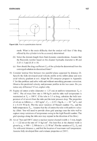
Figure 5.28. Flow in a parallel-plate channel.
mesh. What is the main difficulty that the analyst will face if the drag
offered by the cylinder is to be accurately determined.
(b) Select the domain length from fluid dynamic considerations. Assume that
the Reynolds number based on the channel hydraulic diameter is 40 and
S/R = 3 and B/R = 10.
(c) How should the drag coefficient C D of the cylinder be determined from the
converged solution in discretised form?
18. Consider laminar flow between two parallel plates separated by distance 2b.
Specify the fully developed axial velocity profile at the inflow plane and zero
axial velocity gradient at exit. Adapt the 2D computer program in Appendix
C for this problem and solve with and without smoothing pressure correction.
Observe the predicted velocity and pressure profiles in the two cases. Do you
notice any difference? If not, explain why.
19. Engine oil enters a tube (diameter = 1.25 cm) at uniform temperature T in =
160 C. The oil mass flow rate is 100 kg/hr and the tube wall temperature is
◦
maintained at T w = 100 C. If the tube is 3.5 m long, calculate the bulk tem-
◦
perature of oil at exit from the tube and the total pressure drop. The properties
2
3
of oil are as follows ρ = 823 kg/m , C p = 2,351 J/kg-K, ν = 10 −5 m /s, and
k = 0.134 W/m-K. Plot the axial variation of Nusselt number Nu x and the
bulk temperature T b,x . Assume that the oil enters the tube with uniform veloc-
ity. (Hint: You will need to provide close grid spacings near the tube wall to
capture steep variations of temperature owing to the high Prandtl number. The
grid spacings along the tube axis may expand in the direction of the flow.)
20. Air at 7 bar and 100 C enters a nuclear reactor channel (width = 3 mm, length
◦
2
L = 1.22 m) at the rate of 7.5 kg/s-m . The heat flux at the channel walls is
2
given by q w = 900 + 2,500sin(π x 1 /L) W/m . Plot the variation of T w , T b , and
Nu with axial distance x 1 and find the location of maximum wall temperature.
Assume fully developed flow and evaluate properties at 250 C.
◦