
Page 334 - Introduction to Information Optics
P. 334
6.3. Thin-Film Waveguide Couplers 3 19
To check the precision of numerical calculations the energy balance can be
used. This criteria takes the form
6.3.1.1. Numerical Results
The numerical results presented below are obtained utilizing Eqs. (6.20) and
(6.21). The diffraction grating period is selected to make the angle of the first
diffraction order a 1 equal to a defined value (for example, the bouncing angle
of a waveguide) and cut all other higher-diffraction orders. In reflected light,
only zero-order diffraction exists. All linear sizes are measured in wavelength
value. The diffraction grating has a period 0.9 of the wavelength value.
Substrate refractive index is assumed to be 1.5. Tooth width is selected to be
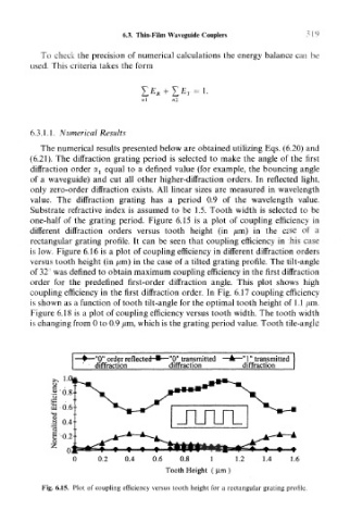
one-half of the grating period. Figure 6.15 is a plot of coupling efficiency in
different diffraction orders versus tooth height (in /mi) in the case of a
rectangular grating profile. It can be seen that coupling efficiency in this case
is low. Figure 6.16 is a plot of coupling efficiency in different diffraction orders
versus tooth height (in /im) in the case of a tilted grating profile. The tilt-angle
of 32° was defined to obtain maximum coupling efficiency in the first diffraction
order for the predefined first-order diffraction angle. This plot shows high
coupling efficiency in the first diffraction order. In Fig. 6.17 coupling efficiency
is shown as a function of tooth tilt-angle for the optimal tooth height of 1.1 /im.
Figure 6.18 is a plot of coupling efficiency versus tooth width. The tooth width
is changing from 0 to 0.9 /mi, which is the grating period value. Tooth tile-angle
-"0" order reflected-*—"0" transmitted -"1" transmitted
diffraction diffraction diffraction
0 0.2 0.4 0.6 0.8 1 1.2 1.4 1.6
Tooth Height (urn)
Fig. 6.15. Plot of coupling efficiency versus tooth height for a rectangular grating profile.