
Page 336 - Introduction to Information Optics
P. 336
6.3. Thin-Film Waveguide Couplers 321
equals the optimal one and tooth height is also optimal. When tooth width
equals zero or period value, only zero-order reflection and refraction radiation
exists. When tooth width is between 0.4 /mi and 0.6 jum, coupling efficiency into
the first diffraction order is very high. This value diapason allows the gratings
to be made with a relatively large tooth width tolerance interval. In the above
case, allowable error equals 0.1/0.5 = 20%, which is very good. The results
demonstrate optimum values of gratings parameters to maximize coupling in
one diffraction order.
6.3.1.2. Experimental Results
6.3.1.2.1. Tilted Grating Profile Fabrication
It is clear that to provide effective free-space-to-waveguide and waveguide-
to-free-space conversions, the mierostructure of the surface-normal grating
coupler shall be tilted to provide the needed phase-matching condition at one
waveguide propagating direction. The tilted angle of the grating corrugation
determines the vertical component of the grating K vector to be built to
provide the required phase-matching condition. In the following, fabrication of
the tilted waveguide grating and some experimental results are described. The
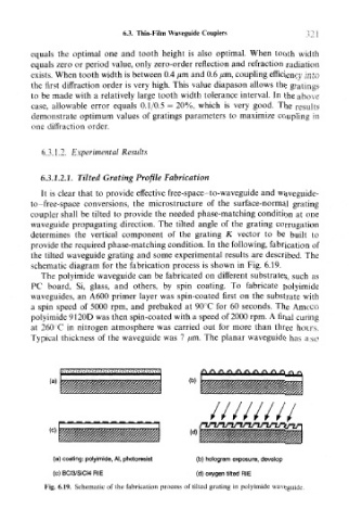
schematic diagram for the fabrication process is shown in Fig. 6.19.
The polyimide waveguide can be fabricated on different substrates, such as
PC board. Si, glass, and others, by spin coating. To fabricate polyimide
waveguides, an A600 primer layer was spin-coated first on the substrate with
a spin speed of 5000 rpm, and prebaked at 90°C for 60 seconds. The Amoco
polyimide 9120D was then spin-coated with a speed of 2000 rprn. A final curing
at 260 C in nitrogen atmosphere was carried out for more than three hours.
Typical thickness of the waveguide was 7 jum. The planar waveguide has also
(a)
(d)
(a) coating: pofyimide, Al, photoresist (b) hologram exposure, develop
(Q) BCI3/SiCl4 RIE (d) oxygen tilted RIE
Fig. 6.19. Schematic of the fabrication process of tilted grating in polyimide waveguide.