
Page 341 - Introduction to Information Optics
P. 341
6. Interconnection with Optics
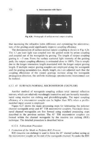
Fig. 6.26. Photograph of surface-normal output coupling.
that increasing the refractive index difference and optimizing the microstruc-
ture of the grating could significantly improve coupling efficiency.
The demonstration of surface-normal output coupling is shown in Fig. 6.26.
The 1.3 /zm laser light was coupled into the guided mode by prism coupling
and coupled out of the waveguide by grating. The length of output coupling
grating is ~3 mm. From the surface scattered light intensity of the guiding
path, the output coupling efficiency is estimated close to 100%. This is simply
due to the longer interaction length associated with the longer output grating
length. If multiple output grating couplers are employed along the waveguide
and the grating parameters (i.e., depth, length, etc.) are adjusted such that the
coupling efficiencies of the output gratings increase along the waveguide
propagation direction, the uniform multistage optoelectronic interconnect can
be realized,
6.3.2. 45 SURFACE-NORMAL MICROMIRROR COUPLERS
Another method of waveguide coupling utilizes total internal reflection
mirrors, which are relatively wavelength insensitive and can be easily manufac-
tured using reactive ion etching and photolithography. The input coupling
efficiency of a micromirror coupler can be higher than 90% when a profile-
matched input source is employed.
Figure 6.27 shows the main processing steps for fabricating the polymer
channel waveguide array and 45° TIR micromirror couplers. Two-layer struc-
tured channel waveguides are first formed using standard processing steps
described in the previous section. The 45° TIR micromirror couplers are
formed within the channel waveguide by the reactive ion etching (RIE)
technique. The detailed procedure is described below
6.3.2.1. Fabrication Procedure
I. Formation of the Mask to Perform RIE Process
RIE (reactive ion etching) is used to form the 45° slanted surface acting as
the micromirror coupler at the end of the waveguide channel. To make the RIE