
Page 354 - Introduction to Information Optics
P. 354
6.6. Optical Clock Signal Distribution
Solid Line: Thin VCSEL
Dashed Line: Thick VCSEL
2.0-
I 1.5- • 1st thin
3rd thin
CL * A 5th thin
V 7th thin
Q.
»-• 1,0- + 9th thin
•f 11st thin
O D 1st thick
O 3rd thick
40 0.5- A 5th thick
(8 V 7th thick
_J
0 9th thick
+ 11st thick
0.0-
2 4 6 8 10 12 14
Bias Current [mA]
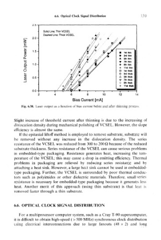
Fig. 6.38. Laser output as a function of bias current before and after thinning proce:
Slight increase of threshold current after thinning is due to the increasing of
dislocation density during mechanical polishing of VCSEL. However, the slope
efficiency is almost the same.
If the epitaxial liftoff method is employed to remove substrate, substrate will
be removed without any increase in the dislocation density. The series
resistance of the VCSEL was reduced from 300 to 200 Q because of the reduced
substrate thickness. Series resistance of the VCSEL can cause serious problems
in embedded-type packaging. Resistance generates heat, increasing the tem-
perature of the VCSEL; this may cause a drop in emitting efficiency. Thermal
problems in packaging are relieved by reducing series resistance and by
attaching a heat sink. However, a large heat sink cannot be used in embedded-
type packaging. Further, the VCSEL is surrounded by poor thermal conduc-
tors such as polyimides or other dielectric materials. Therefore, small series
resistance is necessary for embedded-type packaging because it generates less
heat. Another merit of this approach (using thin substrate) is that heat is
removed faster through a thin substrate.
6.6. OPTICAL CLOCK SIGNAL DISTRIBUTION
For a multiprocessor computer system, such as a Cray T-90 supercomputer,
it is difficult to obtain high-speed (> 500 MHz) synchronous clock distribution
using electrical interconnections due to large fanouts (48 x 2) and long