
Page 326 - Introduction to Marine Engineering
P. 326
300 Instrumentation and control
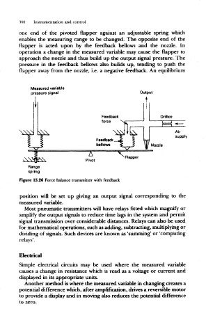
one end of the pivoted flapper against an adjustable spring which
enables the measuring range to be changed. The opposite end of the
flapper is acted upon by the feedback bellows and the nozzle. In
operation a change in the measured variable may cause the flapper to
approach the nozzle and thus build up the output signal pressure. The
pressure in the feedback bellows also builds up, tending to push the
flapper away from the nozzle, i.e. a negative feedback. An equilibrium
Measured variable
pressure signal Output
Feedback
force
Feedback
bellows Nozzle
A
'Flapper
Pivot
Range
spring
Figure 15.26 Force balance transmitter with feedback
position will be set up giving an output signal corresponding to the
measured variable.
Most pneumatic transmitters will have relays fitted which magnify or
amplify the output signals to reduce time lags in the system and permit
signal transmission over considerable distances. Relays can also be used
for mathematical operations, such as adding, subtracting, multiplying or
dividing of signals. Such devices are known as 'summing' or 'computing
relays'.
Electrical
Simple electrical circuits may be used where the measured variable
causes a change in resistance which is read as a voltage or current and
displayed in its appropriate units.
Another method is where the measured variable in changing creates a
potential difference which, after amplification, drives a reversible motor
to provide a display and in moving also reduces the potential difference
to zero.