
Page 325 - Introduction to Marine Engineering
P. 325
Instrumentation and control 299
condition which is compared to the measured value signal. Any
deviation or difference between the two values will result in an output
signal to the controller. The controller will then take action in a manner
related to the deviation and provide a signal to a correcting unit. The
correcting unit will then increase or decrease its effect on the system to
achieve the desired value of the system variable. The comparator is
usually built in to the controller unit.
The transmitter, controller and regulating unit are supplied with an
operating medium in order to function. The operating medium may be
compressed air, hydraulic oil or electricity. For each medium various
types of transmitting devices, controllers and regulating units are used.
Transmitters
Pneumatic
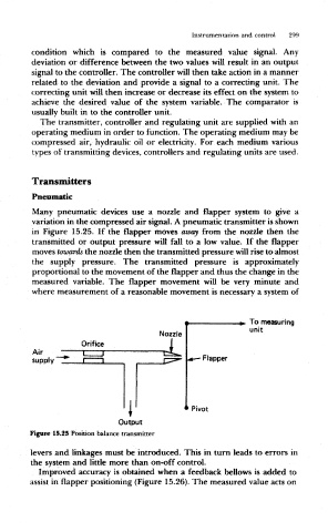
Many pneumatic devices use a nozzle and flapper system to give a
variation in the compressed air signal. A pneumatic transmitter is shown
in Figure 15.25. If the flapper moves away from the nozzle then the
transmitted or output pressure will fall to a low value. If the flapper
moves towards the nozzle then the transmitted pressure will rise to almost
the supply pressure. The transmitted pressure is approximately
proportional to the movement of the flapper and thus the change in the
measured variable. The flapper movement will be very minute and
where measurement of a reasonable movement is necessary a system of
To measuring
unit
Nozzle
Orifice
Air
supply Flapper
Pivot
f
Output
Figure 15.25 Position balance transmitter
levers and linkages must be introduced. This in turn leads to errors in
the system and little more than on-off control.
Improved accuracy is obtained when a feedback bellows is added to
assist in flapper positioning (Figure 15.26). The measured value acts on