
Page 323 - Introduction to Marine Engineering
P. 323
Instrumentation and control 297
gas then passes through a separator, a three-way valve and a flow valve.
The gas sample, after further separation and filtering, passes to the
measuring cell and part of it is bypassed. The flow valve is used to obtain
the correct flow through the measuring cell and a meter provides the
reading of oxygen content. The three-way valve permits the introduc-
tion of a zeroing gas (nitrogen) and a span gas (air). The span gas gives a
21% reading as a calibration check.
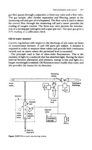
Oil-in-water monitor
Current regulations with respect to the discharge of oily water set limits
of concentration between 15 and 100 parts per million. A monitor is
required in order to measure these values and provide both continuous
records and an alarm where the permitted level is exceeded.
The principle used is that of ultra-violet fluorescence. This is the
emission of light by a molecule that has absorbed light. During the short
interval between absorption and emission, energy is lost and light of a
longer wavelength is emitted. Oil fluoresces more readily than water and
this provides the means for its detection.
Diverting
valves
_
From I W J-, Overboard
tanks discharge
f -A T
V
¥ ^
Monitor
r A , To stop
«-. Sample tank
i
i *"cell
i c/ f <O^ i Desired
1 i ^^ i value
1 Ultra f Photo ' |
violet 1 electric ' i
; lamp 1
u
f I cell | Controller/ n
J recorder
Alar
i Drain to
slop tank
Figure 15.23 Oil-in-water monitoring system