
Page 166 - Introduction to Mineral Exploration
P. 166
7: GEOPHYSICAL METHODS 149
metres
16
8
0
A A’
–8 50 100 150 200 meters
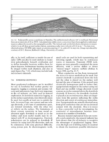
FIG. 7.18 Radar profile across a sand dune in Namibia. The subhorizontal reflector AA′ is rockhead. Horizontal
lines are at intervals of 50 ns TWT. Calculated time shifts (static corrections) have been applied to individual
traces to adjust the record to the topographic profile. The vertical scale on the left shows elevations in meters
−1
relative to an off-dune ground-surface datum, assuming a radar wave velocity of 0.16 m ns . The data were
obtained using a 100 MHz radar signal, an antenna spacing of 1 m, and a 0.5 m step size. (Image reproduced by
courtesy of Dr C. Bristow, Birkbeck College, University of London.)
ally, is, by itself, sufficient to justify the use of small coils are used for both transmitting and
radar. GPR can also be used onshore to locate detecting signals, which may be continuous
river paleochannels beneath overburden and waves or transients. Transient (TEM) tech-
to define favorable locations within them for niques are now generally considered the more
placer deposits. Sedimentary layering can often effective, with a proven ability to detect
be imaged within such channels, and also in “missed target” massive sulfides (Bishop &
sand dunes (Fig. 7.18), which may include beds Lewis 1996, see Fig. 15.7).
rich in heavy minerals. When conductive ore has been intersected,
the mise-à-la-masse method can be used. One
current electrode is positioned down the hole
7.14 BOREHOLE GEOPHYSICS and the other is placed on the surface well
beyond the area of interest. If the ground were
Most geophysical techniques can be modified electrically homogenous (and its surface flat),
for use in boreholes but neither gravity nor equipotentials mapped at the surface using one
magnetic logging is common and seismic vel- fixed and one mobile voltage electrode would
ocity and radiometric logs, both very important contour as circles centered above the downhole
in the oil industry, are little used in mineral electrode. If, however, the downhole electrode
exploration. In downhole resistivity logging, as is placed at an ore intersection, there are depar-
in the surface equivalents, four electrodes must tures from this pattern indicating the strike
be used, but usually at least one is outside the direction and extent of continuous mineralisa-
hole. In normal logs, one current and one volt- tion. Equipotentials are actually diverted away
age electrode, a few tens of centimeters apart, from good conductors that are not in electrical
are lowered downhole, with the other two contact with the electrode. Mise-à-la-masse
at infinity on the surface. The limitations of is thus a powerful tool for investigating the
direct current resistivity in base metal ex- continuity of mineralisation between inter-
ploration apply downhole as much as on the sections in a number of boreholes.
surface and more useful results may be ob- Because mineral exploration holes are norm-
tained with IP or electromagnetics. Electrode ally cored completely, the mineral industry has
polarization can be reduced in downhole IP been slower than the oil industry to recognize
surveys by using lead (Pb) electrodes, and can the advantages of geophysical logging. How-
be eliminated, with some practical difficulty, ever, the high cost of drilling makes it essential
using porous pots. In electromagnetic work, to obtain the maximum possible information