
Page 162 - Introduction to Mineral Exploration
P. 162
7: GEOPHYSICAL METHODS 145
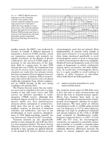
FIG. 7.14 INPUT Mk III transient
response over the Timmins
orebody. Poor quality, large
volume surficial conductors cause Channel 1
large excursions in Channel 1 Channel 2
which die away rapidly at longer
delay times. The orebody response
persists through all four channels. Channel 3
Modern TEM systems may have as
many as 256 channels but the basic
principles remain unchanged. Channel 4
(Data from Barringer Research Inc.,
Toronto.)
another system, the EM37, was produced by electromagnetic work they are induced. More
Geonics in Canada. A different approach to fundamentally, IP systems either sample at
transients is found in UTEM systems, which delay times of from 0.1 to 2 seconds (the initial
use transmitter currents with precisely tri- delay being introduced specifically to avoid
angular waveforms. In the absence of ground electromagnetic noise) or work at frequencies
conductivity, the received UTEM signal, pro- at which electromagnetic effects are negligible.
portional to the time-derivative of the mag- Modern IP units are designed to work over wide
netic field, is a square-wave. In most TEM ranges of frequencies to obtain conductivity
systems (but not UTEM), the transmitter loop spectra, and so necessarily, and often deliber-
can also be used to receive signals since meas- ately, do record some electromagnetic effects,
urements are made after the primary current but it is quite possible to avoid working in
has been terminated. Even if separate loops are regions, of either frequency or time-delay,
used, the absence of primary field at measure- where both effects are both significant.
ment time allows the receiver coil to be placed
within the transmitter loop, which is impract-
ical in CWEM because of the very strong 7.11 REMOTE SOURCE METHODS (VLF AND
coupling to the primary field. MAGNETOTELLURICS)
The Fourier theorem states that any transi-
ent wave can be regarded as the sum of a large Life would be much easier for EM field crews
number of sine and cosine waves, and TEM if they had only to make measurements and
surveys are therefore equivalent to multi- did not also have to transmit primary signals.
frequency CWEM surveys. Although first Efforts have therefore been made to use
developed almost entirely for the detection of virtually all the various existing forms of back-
massive sulfide ores, their multi-frequency ground electromagnetic radiation for geophy-
character allows calculation of conductivity– sical purposes. The most useful are military
depth plots that can be used in studies of transmissions in the 15–25 kHz range (termed
porphyry systems, in detection of stratiform very low frequency or VLF by radio engineers,
orebodies and kimberlites, and even in the although very high by geophysical standards)
development of water resources. Interpreta- and natural radiation in the 10 Hz to 20 kHz
tions of TEM depth-soundings typically use range produced by thunderstorms (audio-
one-dimensional “smooth-model” inversions. frequency magnetotellurics or AMT). In both
Transient methods are also superficially AMT and VLF work, the electromagnetic
similar to time-domain IP, and in IP also there wavefronts are regarded as essentially planar,
is a time–frequency duality. The most obvious and in neither is it possible to measure phase
difference between the electromagnetic and IP differences between primary and secondary
methods is that currents are applied directly radiation. However, differences between the
to the ground in IP surveys whereas in most phases of various magnetic and electrical