
Page 159 - Introduction to Mineral Exploration
P. 159
142 J. MILSOM
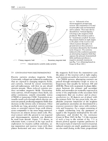
FIG. 7.11 Schematic of an
electromagnetic prospecting
Tx system. The transmitter (Tx) and
Rx
receiver (Rx) coils are horizontal
and co-planar. They may also be
described as “vertical dipoles,”
referring to the magnetic field
produced. The system is said to
be “maximum-coupled” because
the primary field is at right angles
to the plane of the receiver coil
where it passes through it. In
ground surveys this system is
sometimes denoted by the Swedish
term Slingram. The currents
induced in the conductor generate
an alternating magnetic field that
opposes the primary (transmitted)
field, and hence produces a
Primary magnetic field Secondary magnetic field negative anomaly maximum
(see Fig. 7.1c). (Drawing based on
Induced electric currents (eddy currents) Grant & West 1965.)
7.9 CONTINUOUS-WAVE ELECTROMAGNETICS the magnetic field from the transmitter cuts
the plane of the receiver coil at right angles,
Electric currents produce magnetic fields. such systems are said to be maximum-coupled.
Conversely, voltages are induced in conductors In CWEM surveys, alternating currents are
that are exposed to changing magnetic fields, passed through transmitter loops or wires at
and currents, limited by circuit resistivities frequencies that usually lie between 200 and
and self-inductances, will flow in any closed 4000 Hz. There will, in general, be phase differ-
circuits present. These induced currents pro- ences between the primary and secondary
duce secondary magnetic fields. Electromag- fields, and anomalies are normally expressed in
netic surveys, which measure these fields, use terms of the amplitudes of the secondary field
either continuous, usually sinusoidal, waves components that are in-phase and in phase-
(CWEM) or transients (TEM). Transmitters are quadrature (i.e. 90 degrees out of phase) with
usually small coils through which electric cur- the primary field. For any given body, the am-
rents are passed, producing magnetic fields that plitudes (response functions) of the in-phase
decrease as the inverse cube of distance. Other and quadrature anomalies are determined by a
methods use long, grounded, current-carrying response parameter that varies with conduct-
wires or extended current loops with dimen- ivity and frequency. For a target consisting of
sions comparable to the areas being surveyed. a simple conducting loop the parameter is
Receivers are almost always small coils. Phy- equal to the frequency multiplied by the self-
sical contact with the ground is not required inductance and divided by the resistance
and electromagnetic methods can therefore (Grant & West 1965). In Fig. 7.12 the response
be used from aircraft. Figure 7.11 shows, in of such a loop to the system of Fig. 7.11 is
schematic form, a system of the type used in shown plotted against response parameter. If
exploration for massive sulfide orebodies, us- the loop is made of relatively resistive material,
ing transmitter and receiver loops with their induced currents are small, quadrature signals
planes horizontal and axes vertical. Because are also small (being, in the limit, proportional