Page 163 - Introduction to Mineral Exploration
P. 163

146   J. MILSOM


                                                                  In-phase
                                                                  (dip angle)


                                                                      Quadrature


                                                                                  To transmitter

                                                                              E
                                                   Secondary
                                                     field
                                      Dip angle                     H
                                                                                       Dip angle
                                                                    Power
                            Secondary                                   Secondary

                                             Primary                                   Primary
                                                      Primary

                                               Magnetic

                                       Field
                                                                                Secondary
                                                                               magnetic field


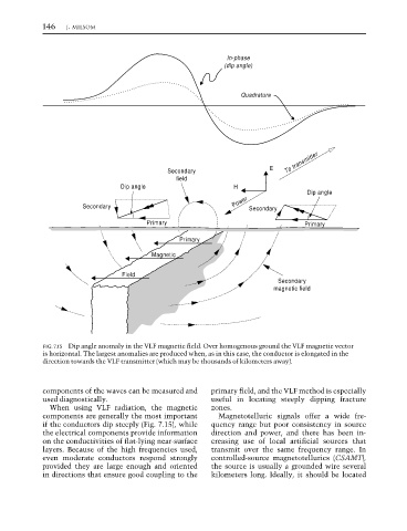
                  FIG. 7.15  Dip angle anomaly in the VLF magnetic field. Over homogenous ground the VLF magnetic vector
                  is horizontal. The largest anomalies are produced when, as in this case, the conductor is elongated in the
                  direction towards the VLF transmitter (which may be thousands of kilometers away).


                  components of the waves can be measured and  primary field, and the VLF method is especially
                  used diagnostically.                        useful in locating steeply dipping fracture
                    When using VLF radiation, the magnetic    zones.
                  components are generally the most important   Magnetotelluric signals offer a wide fre-
                  if the conductors dip steeply (Fig. 7.15), while  quency range but poor consistency in source
                  the electrical components provide information  direction and power, and there has been in-
                  on the conductivities of flat-lying near-surface  creasing use of local artificial sources that
                  layers. Because of the high frequencies used,  transmit over the same frequency range. In
                  even moderate conductors respond strongly   controlled-source magnetotellurics (CSAMT),
                  provided they are large enough and oriented  the source is usually a grounded wire several
                  in directions that ensure good coupling to the  kilometers long. Ideally, it should be located
   158   159   160   161   162   163   164   165   166   167   168