
Page 165 - Introduction to Mineral Exploration
P. 165
148 J. MILSOM
S
i 2
V 1
Head wave
i 2
i c i c
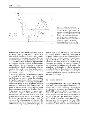
FIG. 7.17 Principles of seismic
refraction for a three layer case. lf
V l < V 2 < V 3 , critical refraction can
occur at both interfaces, producing
planar wavefronts known as “head
Head wave
Sin i 3 = V 1 /V 3
2 i c
waves.” Near to the shot point (S)
Sin 2 i c = V 2 /V 3 V 2
2 i c 2 i c the direct wave will arrive first,
but it will soon be overtaken by the
wave that travels via the first
interface and, eventually, by the
wave that travels via the second.
V 3
individually by hand and sources may need to slowly, back to the surface (Fig. 7.17). Because
be buried. Also, because of the variability of horizontal velocities estimated from plots of
near-surface weathered layers, results require distance against time are used in calculations
sophisticated processing and even then are as if they were vertical velocities, calibration
usually less easy to interpret than marine data. against borehole or other subsurface data is
The use of reflection in onshore exploration for desirable, the more so since an interface may
solid minerals other than coal is consequently be hidden by others if the velocity contrast or
rare, although Witwatersrand gold reefs (see underlying layer thickness is small, and will be
section 14.5.4), flat-lying kimberlite sills (see completely undetectable if velocity decreases
section 17.2), and some deep nickel sulfide with depth. Despite these limitations, there are
bodies have all been investigated in this way many cases, especially in the assessment of
(Eaton et al. 2003). deposits of industrial mineral, where refraction
Refraction methods use simpler equipment surveys can be useful.
and need less processing than reflection
methods but can succeed only if the subsurface
is regularly layered and velocity increases with 7.13 GROUND RADAR
depth at each interface. Generally, only the first
arrivals of energy at each geophone are used, Ground penetrating radar (GPR) is a relatively
minimizing processing but limiting applica- new addition to the geophysical armoury, but
tions to areas with no more than four signi- reports of mineral exploration applications
ficant interfaces at any one locality. Depths are beginning to appear (e.g. Francké & Yelf
to interfaces can be estimated because, except 2003). GPR results are displayed as images very
close to the shot point, where the direct route is similar to those used for seismic reflection
the quickest, the first arrivals will have been work, but penetration is limited to a few tens of
critically refracted. Critically refracted rays can meters at the best, and may stop at the water
be pictured as traveling quite steeply from the table, which is usually a very strong reflector.
surface to the refractor at the overburden velo- In some cases the mapping of the water table,
city, then along the refractor at the velocity which is typically a surface at which the costs
of the underlying layer, and then steeply, and of extracting bulk minerals increase dramatic-