
Page 158 - Introduction to Mineral Exploration
P. 158
7: GEOPHYSICAL METHODS 141
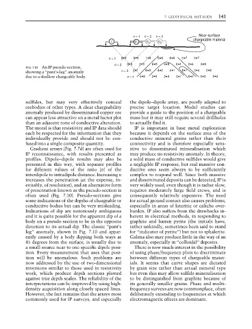
n = 1 n = 2 n = 3 Near-surface
chargeable material
I V 1 V 2 V 3
n = 1 09 06 18 66 66 07 07
n = 2 03 20 69 49 61 04 09
FIG. 7.10 An IP pseudo-section,
showing a “pant’s-leg” anomaly n = 3 21 63 40 41 81 04 08
due to a shallow chargeable body. n = 4 58 39 34 37 92 03 06
sulfides, but may very effectively conceal the dipole–dipole array, are poorly adapted to
orebodies of other types. A clear chargeability precise target location. Model studies can
anomaly produced by disseminated copper ore provide a guide to the position of a chargeable
can appear less attractive on a metal factor plot mass but it may still require several drillholes
than an adjacent zone of conductive alteration. to actually find it.
The moral is that resistivity and IP data should IP is important in base metal exploration
each be respected for the information that they because it depends on the surface area of the
individually provide and should not be con- conductive mineral grains rather than their
fused into a single composite quantity. connectivity and is therefore especially sens-
Gradient arrays (Fig. 7.7d) are often used for itive to disseminated mineralisation which
IP reconnaissance, with results presented as may produce no resistivity anomaly. In theory,
profiles. Dipole–dipole results may also be a solid mass of conductive sulfides would give
presented in this way, with separate profiles a negligible IP response, but real massive con-
for different values of the ratio (n) of the ductive ores seem always to be sufficiently
interdipole to intradipole distance. Increasing n complex to respond well. Since both massive
increases the penetration (at the expense, in- and disseminated deposits can be detected, IP is
evitably, of resolution), and an alternative form very widely used, even though it is rather slow,
of presentation known as the pseudo-section is requires moderately large field crews, and is
often used (Fig. 7.10). Pseudo-sections give consequently relatively expensive. The need
some indications of the depths of chargeable or for actual ground contact also causes problems,
conductive bodies but can be very misleading. especially in areas of lateritic or caliche over-
Indications of dip are notoriously ambiguous burden. IP also suffers from the drawbacks in-
and it is quite possible for the apparent dip of a herent in electrical methods, in responding to
body on a pseudo-section to be in the opposite graphite and barren pyrite (the initials have,
direction to its actual dip. The classic “pant’s rather unkindly, sometimes been said to stand
leg” anomaly, shown in Fig. 7.10 and appar- for “indicator of pyrite”) but not to sphalerite.
ently caused by a body dipping both ways at Galena also may produce little in the way of an
45 degrees from the surface, is usually due to anomaly, especially in “colloidal” deposits.
a small source near to one specific dipole posi- There is now much interest in the possibility
tion. Every measurement that uses that posi- of using phase/frequency plots to discriminate
tion will be anomalous. Such problems are between different types of chargeable mater-
now addressed by the use of two-dimensional ials. It seems that curve shapes are dictated
inversions similar to those used in resistivity by grain size rather than actual mineral type
work, which produce depth sections plotted but even this may allow sulfide mineralisation
against true depth scales. The reliability of the to be distinguished from graphite because of
interpretations can be improved by using high- its generally smaller grains. Phase and multi-
density acquisition along closely spaced lines. frequency surveys are now commonplace, often
However, the fact remains that the arrays most deliberately extending to frequencies at which
commonly used for IP surveys, and especially electromagnetic effects are dominant.