
Page 157 - Introduction to Mineral Exploration
P. 157
140 J. MILSOM
ρ ρ ρ
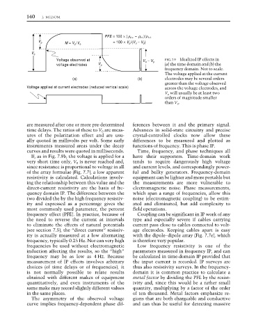
PFE = 100 × (ρ d.c. – ρ h.f. )/ρ h.f.
V p = 100 × V p /(V o − V p )
M = V p /V o
V o
Voltage observed at FIG. 7.9 Idealized IP effects in
V o − V p
voltage electrodes V p (a) the time domain and (b) the
frequency domain. Not to scale.
The voltage applied at the current
(a) (b) electrodes may be several orders
greater than the voltage observed
Voltage applied at current electrodes (reduced vertical scale) across the voltage electrodes, and
V p will usually be at least two
orders of magnitude smaller
than V 0 .
are measured after one or more pre-determined ferences between it and the primary signal.
time delays. The ratios of these to V 0 are meas- Advances in solid-state circuitry and precise
ures of the polarization effect and are usu- crystal-controlled clocks now allow these
ally quoted in millivolts per volt. Some early differences to be measured and plotted as
instruments measured areas under the decay functions of frequency. This is phase IP.
curves and results were quoted in milliseconds. Time, frequency, and phase techniques all
If, as in Fig. 7.9b, the voltage is applied for a have their supporters. Time-domain work
very short time only, V 0 is never reached and, tends to require dangerously high voltage
since resistance is proportional to voltage in all and current levels, and correspondingly power-
of the array formulae (Fig. 7.7), a low apparent ful and bulky generators. Frequency-domain
resistivity is calculated. Calculations involv- equipment can be lighter and more portable but
ing the relationship between this value and the the measurements are more vulnerable to
direct-current resistivity are the basis of fre- electromagnetic noise. Phase measurements,
quency domain IP. The difference between the which span a range of frequencies, allow this
two divided the by the high frequency resistiv- noise (electromagnetic coupling) to be estim-
ity and expressed as a percentage gives the ated and eliminated, but add complexity to
most commonly used parameter, the percent field operations.
frequency effect (PFE). In practice, because of Coupling can be significant in IP work of any
the need to reverse the current at intervals type and especially severe if cables carrying
to eliminate the effects of natural potentials current pass close to cables connected to volt-
(see section 7.5), the “direct current” resistiv- age electrodes. Keeping cables apart is easy
ity is actually measured at a low alternating with the dipole–dipole array (Fig. 7.7e), which
frequency, typically 0.25 Hz. Nor can very high is therefore very popular.
frequencies be used without electromagnetic Low frequency resistivity is one of the
induction affecting the results, so the “high” parameters measured in frequency IP, and can
frequency may be as low as 4 Hz. Because be calculated in time-domain IP provided that
measurement of IP effects involves arbitrary the input current is recorded. IP surveys are
choices (of time delays or of frequencies), it thus also resistivity surveys. In the frequency-
is not normally possible to relate results domain it is common practice to calculate a
obtained with different makes of equipment metal factor by dividing the PFE by the resist-
quantitatively, and even instruments of the ivity and, since this would be a rather small
same make may record slightly different values quantity, multiplying by a factor of the order
in the same places. of ten thousand. Metal factors emphasize re-
The asymmetry of the observed voltage gions that are both chargeable and conductive
curve implies frequency-dependent phase dif- and can thus be useful for detecting massive